Machine Generated Data
Tags
Color Analysis
Feature analysis
Amazon
Clarifai

Clarifai
| Whiteboard | 57.1% | |
Categories
Imagga
created on 2019-05-30
| text visuals | 99.8% | |
Captions
Microsoft
created by unknown on 2019-05-30
| a black sign with white text | 42.3% | |
| a white sign with black text | 42.2% | |
| a black sign with white letters | 36.5% | |
Clarifai
Created by general-english-image-caption-clip on 2025-07-10
floor plan of the house.
Salesforce
Created by general-english-image-caption-blip on 2025-05-15
a photograph of a drawing of a plan for a house
OpenAI GPT
Created by gpt-4o-2024-11-20 on 2025-06-13
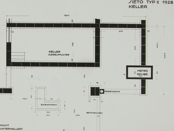
This image is a technical architectural blueprint or plan for the basement ("Keller") of a building labeled "Jietö Typ II 1928." It appears to be a schematic drawing, showing various structural components and measurements, marked in meters (e.g., 2.25, 7.37). Key features include:
- Keller Ziegelplatten: A labeled section that specifies an area made of brick slabs for the basement.
- Metro Grube: A designated section labeled "Metro Grube," likely indicating a pit or sump in the basement.
- Nicht Unterkellert: A section labeled "Not under-basemented," indicating areas without a basement foundation.
- Betonbalken: These are concrete beams, shown with annotations regarding their placement.
- Regenrohr: A rain pipe or drainage pipe appears in the drawing.
- Various measurements and annotations throughout the plan suggest structural dimensions, with thick black lines representing walls or foundations.
The image is minimalistic and focuses on the structural layout, making it useful for architectural or engineering purposes.
Created by gpt-4o-2024-08-06 on 2025-06-13
The image is a technical drawing or blueprint of an architectural plan for a basement (“Keller”) labeled as “SETÖ TYP II 1928.” The drawing features a layout with various labeled components and dimensions. The elements within the drawing include:
- A rectangular area labeled "KELLER ZIEGELPLATER," which likely refers to the basement floor made of brick slabs.
- A smaller rectangle marked as “METRO GRUBE,” possibly indicating a utility space or shaft within the basement.
- The blueprint also includes dimensions alongside the walls, noted in meters, such as "705," "785," "727," and others.
- Areas are labeled with construction terms such as "BETONBALKEN" which means concrete beam.
- A section labeled "NICHT UNTERKELLERT" indicates an area not built over a cellar.
- Additionally, there is a "REGENROHR," which means rainwater pipe, highlighted within the plan.
The overall drawing uses a simple, clean style typical of architectural or engineering schematics, focusing on structure, dimensions, and specific building elements.
Anthropic Claude
Created by anthropic.claude-3-haiku-20240307-v1:0 on 2025-06-17
This image appears to be an architectural floor plan or blueprint. It shows the layout and dimensions of a structure labeled "Aeto Typ II 1928 Keller", which seems to be a basement or cellar level. The plan includes various labeled elements such as "Keller Ziegelplatten" (cellar brick tiles), "Nicht Unterkellert" (not cellared), and a "Metro Gauge" scale. The overall design and technical drawing style suggest this is an engineering or construction document.
Created by us.anthropic.claude-3-5-sonnet-20241022-v2:0 on 2025-06-17
This appears to be an architectural floor plan or basement plan drawing from 1928, labeled "VIETÖ TYP II" by Keller. The drawing shows what appears to be a basement or cellar layout with German labels such as "KELLER" (cellar) and "NICHT UNTERKELLERT" (not basement). The plan includes various rooms and spaces with thick black walls represented by solid lines, and includes detailed measurements and dimensions. The drawing style is typical of architectural documentation from the early 20th century, with clean lines and precise measurements. The layout shows several distinct spaces or rooms connected by passages, with one section specifically marked as not being part of the basement area.
Meta Llama
Created by us.meta.llama3-2-11b-instruct-v1:0 on 2025-06-09
The image presents a floor plan for a building, likely an architectural design or blueprint. The plan is in black and white, with various rooms and spaces labeled in German. The layout includes a large room at the center, surrounded by smaller rooms and corridors. The floor plan also features several doors, windows, and other architectural details.
Key Features:
- Central Room: A large room at the center of the floor plan, possibly a living area or office space.
- Smaller Rooms: Several smaller rooms and corridors surrounding the central room, potentially used for various purposes such as bedrooms, bathrooms, or storage.
- Doors and Windows: Multiple doors and windows are visible throughout the floor plan, indicating the flow of natural light and access to different areas of the building.
- Architectural Details: The floor plan includes various architectural details, such as staircases, hallways, and fireplaces, which provide insight into the building's design and functionality.
Language:
- The floor plan is written in German, suggesting that it may be a design for a building in a German-speaking country or region.
Purpose:
- The purpose of the floor plan is likely to provide a visual representation of the building's layout and design, allowing architects, builders, and other stakeholders to understand the project's scope and requirements.
Conclusion:
The image presents a detailed floor plan for a building, showcasing its layout, architectural features, and potential uses. The use of German language and the inclusion of various rooms and spaces suggest that the building may be designed for a specific purpose or function. Overall, the floor plan provides valuable information for anyone interested in understanding the design and functionality of the building.
Created by us.meta.llama3-2-90b-instruct-v1:0 on 2025-06-09
The image depicts a floor plan for a building, with the title "JIETÖ TYP II 1928 KELLER" in the top-right corner. The floor plan is drawn in black ink on a white background and features various rooms and spaces labeled in German.
Key Features:
- Title: "JIETÖ TYP II 1928 KELLER" (located in the top-right corner)
- Floor Plan: Drawn in black ink on a white background
- Rooms and Spaces: Labeled in German
- Labels: Include "KELLER ZIEGELPFLASTER", "METRO GRUBE", "NIGHT UNTERKELLERT", and others
Overall Impression:
The image appears to be a detailed architectural drawing of a building's basement level, showcasing the layout and design of the space. The use of German labels suggests that the building may be located in Germany or was designed by a German architect.
Amazon Nova
Created by amazon.nova-lite-v1:0 on 2025-06-08
The image appears to be a floor plan or architectural blueprint for a building. It shows a rectangular layout with various rooms and spaces marked. The top left corner has the text "SIETE TYIP II 1928 KELLER," indicating it is a plan for a building called "Sieto Typ II" from the year 1928. The floor plan includes dimensions and measurements in centimeters, likely indicating the scale of the drawing. There are various rooms and spaces labeled, such as "KELLER" (basement), "ZIEGELPLATER" (brick floor), "METRO GRUBE" (metro pit), and "BETONBALKEN" (concrete beam). The plan also shows the location of stairs and other structural elements. Overall, it appears to be a detailed architectural blueprint for a specific building from the year 1928.
Created by amazon.nova-pro-v1:0 on 2025-06-08
The image is a floor plan drawing of a building. The plan is dated 1928 and is labeled "SIETO TYP II." The drawing is a top-down view of the layout of a building's interior, showing various rooms and spaces. The plan is divided into different sections, each labeled with a specific function or name. The rooms include a "KELLER" (basement), "ZIEGELPPLATER" (tiled platform), "METRO GRUBE" (metro pit), "REGENOWA" (possibly a rainwater collection area), "BETONSBALKEN" (concrete beams), "E/ENFUNDAH" (possibly an entrance or foundation), and "NACHUNTRKELERT" (possibly a storage or utility area). The drawing includes dimensions and measurements for each room and space, indicating the size and layout of the building.
Google Gemini
Created by gemini-2.0-flash-lite on 2025-05-09
Here is a description of the image:
The image is a black and white architectural floor plan. The plan is a top-down view of a building's foundation and associated elements. The layout includes several distinct areas with labels in German such as “Keller” (basement), "Nicht Unterkellert" (not basements), and others. The plan features a rectangular main section labeled "KELLER ZIEGELPPLASTER" along with its supporting walls, an adjacent area, and other design elements. Dimensions are indicated with numbers in millimeters and arrows.
The top right corner identifies the design as "SIETÖ TYP II 1928 KELLER". The "METRO GRUBE" and "REGENROHR" labels highlight specific architectural components. The “BETONBALKEN” also appears in multiple locations. The design utilizes thick black lines for walls and key structural elements and the use of dotted lines to indicate measurements and some structures.
Created by gemini-2.0-flash on 2025-05-09
Here's a description of the image:
The image shows a technical drawing, seemingly an architectural plan for a building's basement (Keller). The drawing is titled "SIETÖ TYP II 1928 KELLER".
The plan depicts:
- Keller (Basement): A rectangular area labeled "KELLER ZIEGELPPLASTER" with what looks like a set of stairs in one corner. The thick, dark lines around the perimeter likely represent walls or foundations made of brick (ZIEGELPPLASTER).
- Metro Grube: A smaller area labeled "METRO GRUBE" located near the basement area. The word "GRUBE" translates to "pit" or "excavation", which could be an elevator pit or a similar underground structure.
- Nicht Unterkellert: An area labeled "NICHT UNTERKELLERT", which means "not basemented."
- Additional Features: There are also smaller elements labeled "BETONBALKEN" (concrete beams), "REGENROHR" (rainwater pipe), and "EVENFUNDAM" (perhaps a foundation).
The drawing includes various dimensions indicated by dotted lines and numbers. The layout is functional and schematic, emphasizing measurements and spatial relationships.
Mistral Pixtral
Created by us.mistral.pixtral-large-2502-v1:0 on 2025-05-29
The image is a detailed floor plan of a building labeled "VIETÖ TYP II 1928 KELLER." It appears to be a basement (Keller) layout from 1928, designed in a specific style referred to as "VIETÖ TYP II."
Here is a detailed summary of the floor plan:
Main Sections:
- Keller Ziegelpflaster (Brick Paving Cellar): This is the largest section in the plan, located towards the top right. It is a rectangular space with dimensions approximately 7.85 meters by 5.35 meters.
- Nicht Unterkellert (Not Undercellared): This is another large rectangular section located towards the bottom left. It measures approximately 7.67 meters by 6.45 meters.
Smaller Rooms and Features:
- Metro Grube (Metro Pit): A small rectangular area located near the top right, adjacent to the Keller Ziegelpflaster.
- Eisenpfuhl (Iron Puddle): A small square area situated between the two main sections.
- Besenraum (Broom Room): A small rectangular room located near the center of the plan.
Structural Elements:
- Betonbalken (Concrete Beams): These are indicated in several places, showing structural support beams within the basement layout.
- Walls: The plan shows thick walls, particularly around the perimeter and between different sections.
Dimensions and Measurements:
- The floor plan includes various measurements in meters, providing detailed dimensions for each section and structural element.
Layout and Design:
- The layout is symmetrical and organized, with clear demarcations between different areas.
- The plan uses a combination of solid and dashed lines to indicate walls, beams, and other structural features.
Overall, the floor plan provides a comprehensive view of the basement layout, including the main sections, smaller rooms, structural elements, and precise measurements.
Qwen
Created by Qwen/Qwen2.5-VL-7B-Instruct on 2025-07-04
This image appears to be an architectural floor plan or blueprint, specifically of a basement or cellar, as indicated by the German text "KELLER" which means "basement" in English. The label "METRO GRUBE" suggests a connection to a metro or subway system, possibly a station or a facility related to it. The blueprint is titled "SIEŤÓ TYP II 1928," indicating it is likely a design or plan from that year for a second type of structure or system.
The floor plan includes various labeled areas and dimensions, such as "KELLER ZIEGELPLASTER," which translates to "Basement Tile Plaster," indicating the materials used for the flooring or walls. There are also measurements and markings that specify the dimensions of the rooms, corridors, and structural elements.
The blueprint includes references to "BETONBALKEN," meaning "concrete beams," suggesting the use of reinforced concrete in the construction of the building or facility. There is also a small area labeled "NICKT UNTERKELLERT," which means "not underkilled" or "not underground," which could be a clarification of the basement's position relative to the ground level.
Overall, the image is a detailed technical drawing that provides information about the layout, materials, and dimensions of a basement or underground facility, likely related to a metro station or a similar infrastructure project from the year 1928.
Created by Qwen/Qwen2.5-VL-72B-Instruct on 2025-07-04
This image is a technical architectural drawing showing the layout and details of a basement or cellar ("Keller"), specifically labeled as "Sietö Typ II 1928 Keller." The drawing is a top-down view that includes annotated sections and measurements.
Key Features of the Image:
Layout and Structure:
- The drawing is divided into various sections, with walls represented as thick, black lines.
- The main area is labeled "Keller Ziegelplaster," indicating a cellar with brick plastering.
- There is a smaller section labeled "Metro Grube," which might refer to a metro or utility pit.
Annotations and Labels:
- Various parts of the structure are labeled with text in German, such as:
- "Keller Ziegelplaster" (Cellar with brick plastering).
- "Metro Grube" (Metro pit).
- "Betonbalken" (Concrete beams).
- "Eisenfundament" (Iron foundation).
- "Regenrohr" (Rain pipe).
- "Nicht Unterkellert" (Not cellared).
- Dimensions are annotated throughout the drawing, providing specific measurements for various parts of the structure.
- Various parts of the structure are labeled with text in German, such as:
Lines and Symbols:
- Different types of lines are used to represent various elements, such as solid lines for walls and dashed lines for other features.
- There are symbols indicating specific components, like the rain pipe and the metro pit.
Overall Design:
- The drawing is detailed and precise, typical of architectural blueprints.
- The layout suggests a functional space, possibly for storage or utility purposes, with specific areas designated for different uses.
This technical drawing provides a clear and detailed representation of the cellar's design, including structural elements, materials, and dimensions.
Text analysis
Amazon