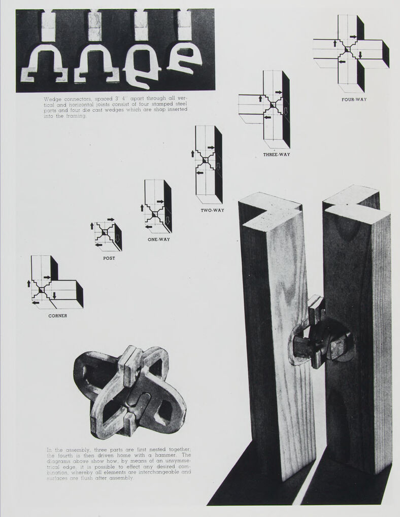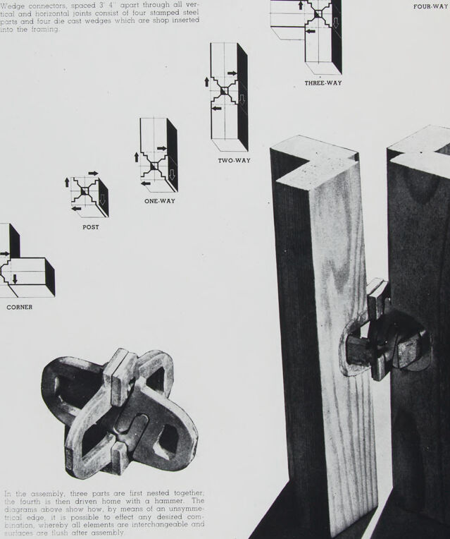
Wedge connectors, spaced 3 4" apart through all ver-
tical and horizontal joints consist of four stamped steel
parts and four die cast wedges which are shop inserted
into the framing
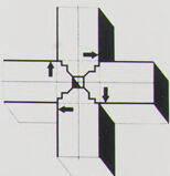
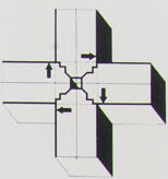
FOUR-WAY
THREE-WAY
Two.wAY
ONE-WAY
POST
CORNER
in the assembly, three parts are first nested together
the fourth is then driven home with a hammer The
diagrams above show how, by means of an unsymme-
trical edge, it is possible to effect any desired com
bination, whereby all elements are interchangeable and
surlaces are lush after assembly