Machine Generated Data
Tags
Color Analysis
Categories
Imagga
| text visuals | 99.8% | |
Captions
Microsoft
created on 2020-04-29
| a close up of text on a whiteboard | 73.4% | |
| a close up of a whiteboard | 73.3% | |
| close up of text on a whiteboard | 70.3% | |
OpenAI GPT
Created by gpt-4 on 2025-03-07
This image shows a hand-drawn sketch, which appears to be a plan or diagram, likely for some construction or woodworking project. There are several rectangles, each labeled with dimensions: "2 x 4" and "3 x 8". The rectangles are connected by lines with additional measurements written in red, such as "15","16", "17", "19 1/4", and "26 1/2". These lines may represent the spacing or placement of the components within the plan. On the right side, there's a small sketch with calculations, possibly rough work related to the diagram. The paper is white with perforations on the left side, suggesting it was torn from a spiral notebook or a similar bound pad. The sketch is simplistic and lacks detail indicating it could be an early stage of planning or brainstorming.
Created by gpt-4o-2024-05-13 on 2025-03-07
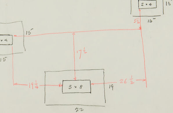
The image appears to be a hand-drawn diagram or sketch with measurements, possibly representing a layout or plan for placing objects or constructing something. Here are the key elements: 1. **Rectangular shapes**: - Three different rectangular shapes are depicted: - Two are labeled "2 x 4" (top left and top right). - One is labeled "3 x 8" (center bottom). 2. **Measurements and lines**: - The diagram includes various measurements written near the lines connecting these rectangles. - The red lines indicate specific distances between the rectangles. The measurements in red are as follows: - The vertical distance between the top left "2 x 4" and the central "3 x 8" is 17 1/2 inches. - The horizontal distance from the top left "2 x 4" to the bottom left line of the overall diagram is 19 1/4 inches. - The horizontal distance from the top right "2 x 4" to the bottom right line of the overall diagram is 26 1/2 inches. - The distance from the center-bottom "3 x 8" to the bottom edge of the diagram is marked as 22 inches in gray pencil. - The vertical distance between the top left "2 x 4" and the bottom left area of the diagram is marked as 15 inches. - The horizontal distance between the top right "2 x 4" and the bottom right area of the diagram is marked as 15 inches. - The small vertical distance noted next to the top right "2 x 4" is 5 1/4 inches. 3. **Labels and Annotations**: - There are some annotations, scribbles, and possibly mathematical calculations on the right side of the paper, though they are partially illegible and seem to have some mathematical relevance. Overall, this is a schematic representation with specific measurements, likely used for construction or placement planning of rectangular objects.
Anthropic Claude
Created by claude-3-5-sonnet-20241022 on 2025-01-19
This image appears to be a hand-drawn floor plan or layout sketch on notebook paper. It shows three rectangular spaces arranged in a layout, with measurements written in red and black. Two spaces are labeled "2 x 4" and one larger space is labeled "3 x 8". The measurements around the perimeter include dimensions like "15", "19", "22", and "26½". The sketch includes connecting lines showing how the spaces relate to each other, with one space centered below two others. The lines appear to be drawn in both black (for the room outlines) and red (for measurement lines).
Created by claude-3-opus-20240229 on 2025-01-19
The image shows a hand-drawn diagram or sketch on ruled paper. The diagram consists of several rectangular boxes of different sizes, with dimensions marked in red. The dimensions appear to be in pairs, likely indicating length and width measurements of each box, such as "2 x 4", "3 x 8", etc. The boxes are arranged in a layout that suggests they may represent rooms or sections of a building plan or blueprint. The sketch has additional handwritten notes and markings in the bottom right corner.
Created by claude-3-haiku-20240307 on 2025-01-19
The image appears to be a hand-drawn diagram or sketch. It consists of several rectangular shapes with dimensions labeled, as well as some connecting lines and measurements. The shapes seem to represent different geometric objects or components, but without any additional context, I cannot determine the specific purpose or meaning of this diagram.
Meta Llama
Created by us.meta.llama3-2-90b-instruct-v1:0 on 2025-01-19
The image depicts a graphic with text and a logo, featuring a predominantly white background with black text. The logo is situated on the left side of the image, while the text is positioned on the right. **Logo:** The logo consists of a stylized letter "A" or "V" with a curved line underneath it, resembling a wave or a swoosh. The logo is rendered in a light brown color. **Text:** The text is written in a bold, sans-serif font and reads "system". It is also light brown in color. **Background:** The background of the image is a solid white color, providing a clean and simple backdrop for the logo and text.
Created by us.meta.llama3-2-11b-instruct-v1:0 on 2025-01-19
The image depicts a hand-drawn diagram on a piece of paper, featuring a series of rectangles with measurements and labels. The diagram appears to be a technical drawing, possibly for a building or architectural project. Here are the key elements of the diagram: * **Rectangles:** * There are five rectangles in total, each with a unique size and label. * The rectangles are drawn in black ink, with some having red lines and numbers added to them. * The labels on the rectangles include "2x4", "3x8", and "2x4", which may indicate the dimensions or type of material used. * **Measurements:** * The diagram includes various measurements, such as lengths, widths, and heights, which are written in red ink. * Some of the measurements are labeled with arrows, indicating the direction of the measurement. * **Labels:** * The labels on the rectangles and measurements provide additional information about the diagram. * The labels may indicate the purpose or function of each rectangle, such as a wall, floor, or roof. * **Background:** * The background of the diagram is a plain white paper, with a few faint marks or smudges visible. * The paper appears to be a standard A4 size, with a perforated edge on the left side. Overall, the diagram appears to be a technical drawing created by an architect or engineer to plan and design a building or structure. The use of rectangles, measurements, and labels provides a clear and detailed representation of the project's layout and specifications.
Amazon Nova
Created by amazon.nova-lite-v1:0 on 2025-01-19
The image shows a sketch of a diagram on a white sheet of paper with a grid pattern. The diagram is drawn in red and black ink and includes various shapes and lines. It appears to be a technical drawing or blueprint, possibly related to engineering or architecture. The diagram includes measurements and annotations in red ink, indicating dimensions and specifications. The overall composition of the diagram is complex, with multiple intersecting lines and shapes.
Created by amazon.nova-pro-v1:0 on 2025-01-19
The image shows a sketch of a rectangular shape with a grid-like structure on a white background. The sketch is drawn in red and black colors. The rectangular shape has a 2x4 grid, with each square measuring 15 units. The grid is divided into four equal parts, with each part measuring 17 units. The sketch also includes a 3x8 grid, with each square measuring 19 units.
Text analysis
Amazon