Machine Generated Data
Tags
Color Analysis
Feature analysis
Amazon
Clarifai
AWS Rekognition
| Airplane | 84.4% | |


Categories
Imagga
created on 2020-04-25
| paintings art | 80% | |
| text visuals | 19.3% | |
Captions
Microsoft
created by unknown on 2020-04-25
| a close up of text on a white surface | 55.1% | |
| a white sign with black text | 37.8% | |
| close up of text on a white surface | 37.7% | |
Clarifai
No captions written
Salesforce
Created by general-english-image-caption-blip-2 on 2025-06-30
a drawing of a cube with a line drawing of the same
Created by general-english-image-caption-blip on 2025-05-04
a photograph of a drawing of a drawing of a building
OpenAI GPT
Created by gpt-4 on 2024-12-14
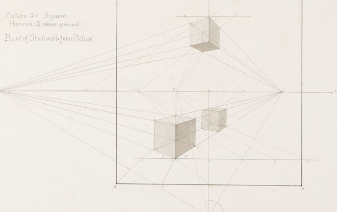
This is a technical drawing featuring a perspective exercise. At the center of the image is a larger drawing with a caption "LECTURE II" at the top and annotations indicating "Picture 2Ft Square Horizon 1 Ft above ground Point of Station 2ym P.Curve". The drawing shows a set of lines converging towards a vanishing point on the horizon line, illustrating the principles of linear perspective as they relate to rendering three-dimensional shapes on a two-dimensional surface. A cube-like structure is presented in this perspective demonstration.
To the right of the central drawing, there are two smaller technical drawings labeled "ELEVATION" and "PLAN," which represent the frontal view and the top-down view (respectively) of the three-dimensional shape seen in perspective in the larger drawing. The elevation and plan show orthogonal views, meaning they illustrate the object without the distortion of perspective.
The entire composition appears to be a study or educational material related to the fundamentals of perspective drawing, which is a key concept in art, architecture, and design education.
Created by gpt-4o-2024-05-13 on 2024-12-14
This image is a technical drawing illustrating principles of perspective, likely for an educational purpose as indicated by the title "Lecture II" at the top.
Key features of the drawing:
- The central part of the image features a large square, within which two three-dimensional cubes are drawn, demonstrating how objects appear smaller as they recede into space.
- Lines extend from points on the left side of the image to various points on the cubes, converging at a single point outside of the large square, representing the vanishing point.
- On the left upper side of the square, annotations indicate "Picture 24√2 Square," "Horizon 12√ above ground,” and “Point of Station 18√ from Picture.”
- In the lower right region of the image, there is a smaller diagram labeled "ELEVATION" and "PLAN," showing different views (side and top view) of the cubes with additional construction lines for accurate placement.
The image shows how perspective drawing techniques are used to create the illusion of depth and space in two-dimensional representations.
Anthropic Claude
Created by us.anthropic.claude-3-5-sonnet-20241022-v2:0 on 2025-06-25
This image appears to be a technical drawing or architectural diagram labeled "LECTURE II" at the top. It shows a perspective drawing exercise demonstrating how to draw cubes in space using perspective lines and vanishing points. The main drawing shows two cubes at different positions in perspective, with construction lines radiating from vanishing points to create the three-dimensional effect. On the right side of the drawing are smaller supplementary diagrams showing what appears to be an elevation and plan view of the objects. The drawing is done in a precise, technical style with light pencil lines, and includes some text notes, including "Picture 24° Square" and "Point of Station 15 from Picture" written in the top left corner. This appears to be an instructional diagram used to teach principles of perspective drawing.
Created by claude-3-haiku-20240307 on 2024-12-14
The image appears to be a technical drawing or diagram labeled "Lecture II". It depicts a perspective grid with various geometric shapes and lines. The shapes include a cube and possibly other rectilinear objects. The grid and lines seem to represent a system of perspective, likely used for teaching or demonstrating principles of spatial representation and visual perception. The overall composition has an architectural or technical illustration style.
Created by claude-3-5-sonnet-20241022 on 2024-12-14
This is a technical drawing titled "Lecture III" that appears to be focused on perspective and geometric principles. The drawing shows two cube-like shapes arranged in space with various perspective lines radiating from a vanishing point. The image includes additional reference diagrams on the right side showing an elevation and plan view. There's text at the top that reads "Picture 24" and "Square Horizon 12 above ground." The drawing is executed in a precise, architectural style with light pencil or ink lines. It appears to be an instructional or educational illustration demonstrating principles of perspective drawing and spatial representation.
Meta Llama
Created by us.meta.llama3-2-11b-instruct-v1:0 on 2024-12-14
The image presents a technical drawing of a cube, accompanied by various geometric shapes and lines. The drawing is rendered in black ink on white paper, with the title "LECTURE II" inscribed at the top center.
Key Features:
- Cube: The central element of the drawing is a cube, depicted in three dimensions with lines extending from its vertices to form a 3D representation.
- Geometric Shapes: Various geometric shapes are scattered throughout the drawing, including triangles, squares, and circles, which serve to illustrate the cube's dimensions and relationships to other shapes.
- Lines: Lines of varying thickness and style are used to connect the cube to other shapes and to provide additional context for the drawing.
- Text: The text "Picture 24: Square Horizon 2 above ground Point of Stationary from Picture" is written in the top-left corner, while the word "ELEVATION" is positioned in the bottom-right corner, accompanied by a small diagram.
- Scale: A scale is included at the bottom of the page, featuring measurements in inches and feet.
Overall Impression:
The drawing exudes a sense of precision and attention to detail, suggesting that it was created for educational or instructional purposes. The use of technical terms and the inclusion of a scale imply that the drawing is intended to convey complex information in a clear and concise manner.
Created by us.meta.llama3-2-90b-instruct-v1:0 on 2024-12-14
The image presents a technical drawing of a cube, accompanied by various geometric lines and labels. The drawing is titled "Lecture III" at the top center, with the main focus being a cube situated within a square frame. The cube is depicted in three dimensions, with its front face facing the viewer and its back face visible through the transparent front face.
The drawing features several lines extending from the cube to the edges of the square frame, which are labeled with letters such as "A," "B," and "C." These lines appear to be perspective lines, used to create the illusion of depth on a two-dimensional surface. Additionally, there are several other lines and shapes present in the drawing, including a smaller cube in the upper right corner and a series of curved lines in the lower right corner.
The background of the drawing is a light beige color, providing a clean and neutral backdrop for the technical details. Overall, the image appears to be a instructional or educational tool, likely used to teach students about perspective drawing and geometric shapes.
Amazon Nova
Created by amazon.nova-lite-v1:0 on 2025-01-12
This image appears to be a diagram or illustration from a lecture or presentation on perspective drawing. The main image shows a cube drawn in perspective, with lines extending from the cube to represent the vanishing point and horizon line. The text "LECTURE II" is displayed at the top, indicating this is the second lecture in a series.
The diagram is divided into three main sections:
The central section shows the cube drawn in perspective, with lines extending from the cube to the vanishing point on the horizon line. The horizon line is marked as being 12 inches above the ground.
The left section provides an elevation view of the cube, showing its height and dimensions from the side.
The right section provides a plan view of the cube, showing its dimensions from above.
The image also includes a small diagram in the bottom right corner, which appears to be a key or legend explaining the different elements in the main diagram.
Overall, the image is a visual aid to help explain the principles of perspective drawing, specifically how to draw a cube in perspective using a vanishing point and horizon line. The inclusion of elevation and plan views provides additional context and information about the cube's dimensions.
Created by amazon.nova-pro-v1:0 on 2025-01-12
The image is a drawing of a cube with a square on top of it, and the words "Lecture II" are written at the top. The drawing is on a white background. The cube is drawn in perspective, with the square on top of it. The drawing also includes a grid, with the words "Elevation" and "Plan" written on the right side. The drawing is titled "Picture 24: Square Horizon 12 above ground Point of Stationary Point Picture."
Google Gemini
Created by gemini-2.0-flash-lite on 2025-05-04
This is a technical drawing or illustration, likely a lesson on perspective drawing. Here's a breakdown:
Overall Composition:
- The image is a detailed sketch on a sheet of paper with a pale, neutral tone.
- It is divided into several sections, each demonstrating different aspects of the perspective process.
- The primary area features a large square in which the central subject is drawn, as well as cubes floating in perspective.
- There is text with information in the image and some other geometrical shapes that could illustrate technical details.
Key Elements and Their Function:
- Central Square: A large, labeled square is positioned in the central section. This is the frame of the scene.
- Horizon Line: A horizontal line labeled "V" (vanishing point) is drawn through the center of the square. This is the line where parallel lines converge.
- Vanishing Point: The "V" marks the location where lines converge in perspective. It is the focal point of the drawing.
- Cubes: Several cubes are drawn within the frame. They illustrate how objects appear smaller and recede into the distance in a perspective view.
- Construction Lines: Numerous lines radiate from the vanishing point and are used to create the effect of depth and how the objects relate to one another.
- Additional Geometric Shapes: There are other figures that give context, like a circle.
- Titles and Labels: Text is present, including "Lecture III", "Picture 24: Square," and labels and markings (letters and numbers) that guide the construction and explain the relationships between elements in the drawing.
Interpretation:
- The drawing serves as a learning aid, demonstrating the principles of one-point perspective.
- The drawing uses the rules of this perspective to depict how geometric figures appear in space.
- The technique is commonly used by architects and technical drafters.
Created by gemini-2.0-flash on 2025-05-04
The image appears to be a technical drawing or diagram related to perspective and possibly geometry. It includes the following elements:
- Text and Annotations: There's text in the top left indicating "Picture 24 Square," "Horizon 12 above ground," and "Point of Stationtopom Picture." The main title "LECTURE II" is above the central diagram. Other annotations like "ELEVATION" and "PLAN" are also present on the right side.
- Geometric Shapes: The main part of the image includes cubes or squares drawn in perspective. There are three cubes, one floating above and two at eye level.
- Horizon Line and Vanishing Points: A horizontal line is drawn across the center, indicating the horizon. The drawing uses the concept of vanishing points to depict perspective, with lines converging towards points on the horizon.
- Technical Drawing Lines: The image includes numerous lines, both solid and dashed, used to illustrate the geometric construction and relationships between the shapes and the perspective.
- Additional Diagrams: On the right, there are elevation and plan diagrams showing the projection and orientation of a square or cube.
- Background: The background appears to be a plain, off-white or cream-colored paper.
Overall, this image seems to be from an instructional or educational context, likely related to teaching principles of drawing, perspective, or geometry.
Mistral Pixtral
Created by us.mistral.pixtral-large-2502-v1:0 on 2025-06-01
The image is a technical drawing related to a lecture, specifically "Lecture III." It depicts a perspective drawing of a square viewed from above ground level, with the horizon line 14 units above the ground. The title of the drawing is "Bird's Eye View from Above."
Here are the key elements of the drawing:
Title and Description:
- The drawing is labeled "Lecture III."
- It is described as a "Picture of Square Horizon 14 units above ground Bird's Eye View from Above."
Main Diagram:
- The main part of the drawing shows a square with a grid overlay.
- Inside the square, there are two cubes positioned at different heights and angles, illustrating three-dimensional perspective.
- Lines extend from the edges of the cubes to points outside the square, demonstrating the principles of perspective drawing.
Perspective Lines:
- The lines converge to vanishing points, which are typical in perspective drawings to create the illusion of depth and three-dimensional space.
Elevation and Plan:
- To the right of the main diagram, there is a smaller diagram showing the elevation and plan views of one of the cubes.
- The elevation view shows the side view of the cube, while the plan view shows the top-down view.
Labeling:
- The drawing includes labels such as "ELEVATION" and "PLAN" to indicate the different views.
- There are also numerical and alphabetical annotations (e.g., "A," "B," "14") that likely correspond to specific measurements or points in the drawing.
Overall, the image is a detailed technical illustration used to teach the principles of perspective drawing, specifically from a bird's-eye view above the ground.
Qwen
Created by Qwen/Qwen2.5-VL-7B-Instruct on 2025-07-10
The image appears to be a technical drawing or diagram from a lecture, specifically labeled as "Lecture III." The drawing is titled "Picture 2" and describes a square with the horizon 12 units above the ground. The diagram illustrates the concept of perspective drawing, where a cube is depicted in three-dimensional space. The cube is shown in various projected views, including an elevation and a plan view, which are located to the right of the main square image.
The drawing includes numerous lines that represent the vanishing points and the lines of sight from the point of projection to the cube. These lines demonstrate how the cube's dimensions are reduced in size as they approach the horizon line, creating a realistic three-dimensional effect on a two-dimensional plane.
The diagram is detailed, with labels and measurements to help understand the perspective calculation. The "Point of Station" is mentioned, which is the position from which the drawing is being projected. The overall style and content suggest it is an educational illustration, likely from an architectural or design curriculum.
Created by Qwen/Qwen2.5-VL-72B-Instruct on 2025-07-10
This image is a technical drawing or illustration titled "Lecture III," which appears to be a study in perspective drawing. The drawing is done on a white background with black lines and gray shading.
Central Drawing: The main part of the drawing shows three cubes in perspective within a rectangular frame. The cubes are depicted at different depths, and the lines of perspective converge towards a vanishing point outside the frame on the left side. The cubes are shaded to give a sense of three-dimensionality.
Top Left Text: There is text on the top left that reads "Picture 24: Square Horizon 12 above ground Point of Station 4 from Picture," indicating the parameters of the perspective drawing.
Right Side Drawings: On the right side of the main drawing, there are smaller drawings labeled "ELEVATION" and "PLAN." The elevation drawing shows the side view of a cube, while the plan drawing shows the top view of a cube, along with some additional geometric shapes.
Overall Layout: The drawing is well-organized with clear labels and annotations, suggesting it is part of a series of lectures or instructional materials on perspective drawing techniques. The precision of the lines and the use of perspective indicate a focus on architectural or engineering drawing principles.
Text analysis
Amazon