Machine Generated Data
Tags
Color Analysis
Feature analysis
Amazon
| White Board | 96.4% | |

Categories
Imagga
| text visuals | 100% | |
Captions
Microsoft
created on 2018-08-23
| a flock of seagulls flying in the sky | 28.9% | |
| a flock of birds flying in the sky | 28.8% | |
| a flock of seagulls flying around | 28.7% | |
OpenAI GPT
Created by gpt-4 on 2025-03-06
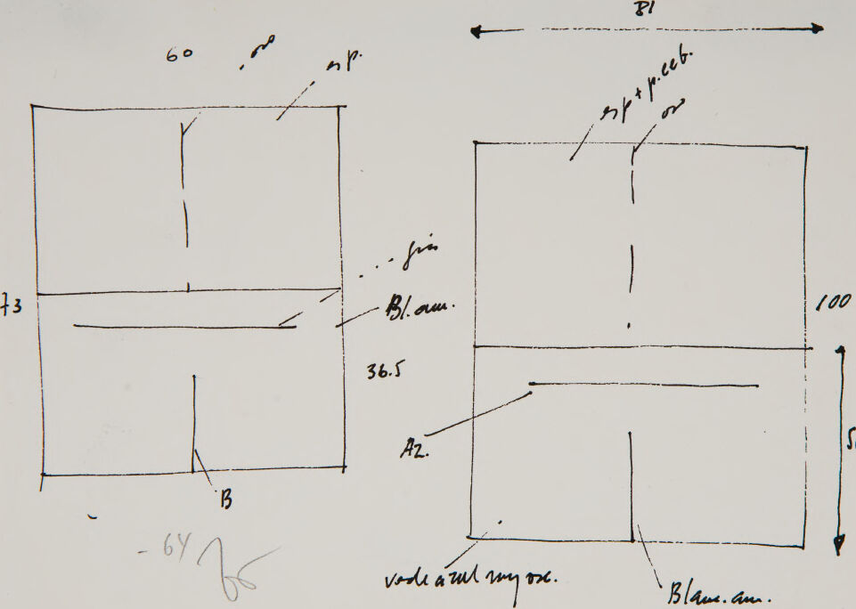
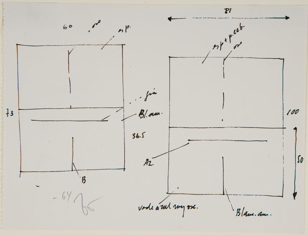
This image displays a hand-drawn sketch of two square or rectangular shapes with lines demarcating what appears to be dimensions or divisions within these shapes. Around the sketch, there are handwritten annotations, which may represent measurements, notes, or instructions related to the drawn figures. There are numbers near each segment of the lines, possibly indicating lengths or positions. The annotations are not entirely legible, but they seem to include both numerical values and text. The sketch and the annotations have the character of preliminary design work or planning, as might be seen in architectural, engineering, or product design drawings. There is a signature or some sort of scribble in the lower left corner, which could indicate approval or creation by a specific person. The background is white, and the medium appears to be ink on paper. The drawing is simplistic and lacks ornamental detail, emphasizing functionality or conceptualization over aesthetic presentation.
Created by gpt-4o-2024-05-13 on 2025-03-06
The image is a hand-drawn sketch that appears to be a detailed plan or diagram with annotations and measurements. It consists of two rectangular sections, one above the other. Key features of the drawing include: 1. **Dimensions**: The upper section is labeled with a width of 60 units and a height of 73 units on the left side. The total width of both sections together is marked as 81 units, and the overall height as 100 units on the right side, with the lower section noted as being 50 units in height. 2. **Labels and annotations**: Various handwritten notations are present, including "m/p" at the top of the upper section, "36.5" in the middle right next to the middle line separating the two sections, "Bl.aus." on the right side near the division between sections, and "voile aul my occ." along with "Blanc.aus." at the bottom right of the lower section. 3. **Lines and subdivisions**: Within each rectangular section, there are additional lines subdividing each section. The upper rectangle is divided with a vertical and a horizontal line. Similarly, the lower rectangle is divided with a vertical and a horizontal line. 4. **Miscellaneous**: There is a small annotation "- 6Y\s" at the bottom left corner of the image, possibly a residual mark or signature. Overall, the sketch seems to be a technical diagram that specifies measurements and certain instructions or labels associated with each part of the divided rectangles.
Anthropic Claude
Created by claude-3-haiku-20240307 on 2025-01-21
The image appears to be a technical diagram or schematic. It contains various geometric shapes, labels, and measurements. The diagram seems to depict some kind of technical or engineering-related information, but without more context, I cannot determine the specific subject or purpose of the diagram.
Created by claude-3-5-sonnet-20241022 on 2025-01-21
This appears to be a technical drawing or sketch showing two similar square or rectangular diagrams side by side. The left diagram is labeled with "60" and "73" measurements, while the right diagram shows "100" and "50" measurements. Both diagrams have internal lines and markings, including what appears to be "B" markings. There are some additional annotations and measurements written in between and around the diagrams, including what looks like "36.5" and some other handwritten notes. The overall style suggests this might be an architectural sketch or planning diagram of some kind.
Created by claude-3-opus-20240229 on 2025-01-21
The image shows a rough pencil sketch with dimensions and notes. It appears to depict plans or schematics for constructing some type of rectangular object or structure. The sketch includes measurements in centimeters along the edges and diagonal lines. There are also a few brief handwritten notes on the sketch, though the handwriting is a bit difficult to decipher. Overall, it looks like an initial concept drawing or brainstorming sketch capturing key dimensions and design ideas for a project.
Meta Llama
Created by us.meta.llama3-2-90b-instruct-v1:0 on 2025-01-21
The image presents a hand-drawn diagram on white paper, featuring two rectangular shapes with various lines and measurements. The left rectangle is labeled "73" at the bottom, while the right rectangle is labeled "100" on the right side. Both rectangles have a horizontal line near the top, accompanied by additional lines and notations throughout. The diagram appears to be a technical drawing or blueprint, likely created for architectural or engineering purposes. The use of precise measurements and labels suggests that the diagram is intended to convey specific information about the design or layout of a structure or system. Overall, the image provides a detailed and informative visual representation of a technical concept, making it a valuable resource for professionals and students in related fields.
Created by us.meta.llama3-2-11b-instruct-v1:0 on 2025-01-21
The image presents a hand-drawn diagram on white paper, featuring two rectangles with various measurements and annotations. The left rectangle is labeled "60" at the top and "13" on the left side, while the right rectangle is labeled "81" at the top and "100" on the right side. Both rectangles have a smaller rectangle within them, with the left one labeled "36.5" and the right one labeled "50." The diagram also includes several lines and arrows connecting the rectangles, as well as handwritten notes in an unknown language. **Key Features:** * **Rectangles:** Two rectangles are drawn on the paper, each with its own set of measurements and annotations. * **Measurements:** The rectangles are labeled with various measurements, including "60," "13," "81," "100," "36.5," and "50." * **Annotations:** The diagram includes several lines and arrows connecting the rectangles, as well as handwritten notes in an unknown language. * **Language:** The language used in the annotations is not recognizable, making it difficult to determine the meaning of the diagram. **Overall Impression:** The diagram appears to be a technical drawing or blueprint, possibly used for architectural or engineering purposes. The use of precise measurements and annotations suggests that the diagram is intended to convey specific information about the design or structure being represented. However, without further context or information about the language used, it is difficult to provide a more detailed interpretation of the diagram.
Amazon Nova
Created by amazon.nova-lite-v1:0 on 2025-01-12
The image depicts a technical drawing or architectural sketch, primarily in black ink on a white background. The sketch shows a detailed plan or section of a structure, likely a building or a room. The drawing includes various measurements and annotations, with dimensions marked in both metric and imperial units. Notable measurements include "60" and "100" in one part of the drawing, and "50" in another. The drawing also includes labels such as "B1," "B2," and "A2," which likely refer to specific areas or components within the structure. There are also notes and annotations in French, indicating the designer's origin or the intended audience. The sketch is divided into sections, with a focus on the structural layout and possibly the placement of windows or other architectural features.
Created by amazon.nova-pro-v1:0 on 2025-01-12
The image shows a piece of paper with a technical drawing and handwritten notes. The drawing appears to be a schematic or diagram, possibly related to engineering or architecture. The drawing includes lines, boxes, and labels, indicating different components or measurements. The handwritten notes are written in cursive and include various measurements, such as "60," "36.5," "100," and "50," as well as abbreviations like "np," "B1," and "A2." The notes also include the word "Blam," which could be a reference to a specific component or measurement.
Created by amazon.nova-pro-v1:0 on 2025-01-21
The image shows a white sheet of paper with a black-and-white drawing of a rectangular structure. The drawing is labeled with measurements and annotations, indicating that it is a technical drawing or blueprint. The rectangular structure is divided into two sections, with the left section labeled "B1" and the right section labeled "B2." The drawing also includes measurements and annotations, such as "60" and "100," which likely represent dimensions or specifications.
Created by amazon.nova-lite-v1:0 on 2025-01-21
The image is a technical drawing or blueprint, likely related to architectural or engineering design. The drawing features two main sections, each containing various measurements and annotations. The left section has a rectangular shape with measurements of 60, 36.5, and 73, possibly indicating dimensions of a structure or component. The right section is more complex, with multiple lines and measurements, including 100, 50, and 36.5, which could represent different parts or features of a design. The text includes abbreviations and numbers, such as "B1," "B2," and "B3," which might refer to specific components or sections of the design. The drawing is handwritten, suggesting it is a draft or preliminary design.
Text analysis
Amazon