Machine Generated Data
Tags
Color Analysis
Categories
Imagga
| text visuals | 97.7% | |
| paintings art | 2.2% | |
Captions
Microsoft
created on 2020-04-30
| a close up of text on a white background | 80.2% | |
| a close up of text on a white surface | 78.2% | |
| a close up of text on a black background | 74.9% | |
OpenAI GPT
Created by gpt-4 on 2025-03-07
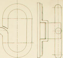
This image displays a technical drawing or mechanical blueprint of what appears to be a machine part or assembly. The drawing is executed with precision, using fine lines, hatches, and geometric shapes to define the object in detail. To the right side of the page, there is text that reads "BERTRAND GOLDBERG MECHANISM 27 Dec. 1932 SCHEMAT," suggesting that this is a mechanism designed by Bertrand Goldberg, dated December 27, 1932, and the drawing represents a schematic view of it. The sketch is laid out on a large sheet with a light background, and the lines are drawn in a dark color, likely black. The drawing consists of multiple views including front, side, and top, providing different perspectives for understanding the mechanism's design. There are also several circles with centerlines, which typically represent holes or cylindrical features, and there are various geometric shapes with dimension lines and text that likely detail sizes and other specifications necessary for manufacturing or construction.
Created by gpt-4o-2024-05-13 on 2025-03-07
The image depicts a technical drawing, likely a mechanical or architectural blueprint. The drawing is detailed and precise, featuring a top-down view and a side view of a mechanical component that seems to involve a sliding mechanism or assembly. Key elements in the drawing include: 1. **Rectangular Plates** - There are rectangular plates depicted with multiple evenly spaced circular holes, perhaps for fastening bolts or screws. 2. **Cutaway Section** - A portion of the rectangular plate is shown with a zigzag cut pattern, suggesting a sectional view to reveal internal details. 3. **Curved Component** - A significant component has a pronounced curved shape, possibly a handle or lever that is part of the moving mechanism. 4. **Linear Elements** - There are elongated straight lines indicating components that may slide or move in relation to each other. 5. **Annotated Dimensions** - The drawing is marked with cross-section lines and detailed measurements or labels (not fully legible in the image provided). 6. **Text Information** - There is a text block in the lower right corner that contains the name "Bertrand Goldberg," date "29 Dez, 1932," and German words “MECHANIK” and “SCHIEBAR,” which translate to "mechanics" and "sliding" respectively. The drawing is technical, containing precision measurements and annotations typical of mechanical engineering or architectural design. It illustrates both the structural and functional aspects of the depicted component.
Anthropic Claude
Created by claude-3-opus-20240229 on 2025-01-20
The image shows a technical schematic or blueprint diagram. It consists of various geometric shapes, lines, and symbols arranged in a specific layout on the page. The shapes include rectangles and circles of different sizes, connected by straight lines. Below the main diagram, there appears to be a smaller, more detailed view or cross-section of part of the design. The text at the bottom identifies this as a "BERTRAND-GOLDBERG MECHANICAL STORAGE SCHEME", suggesting it is an architectural or engineering plan created by or attributed to someone named Bertrand Goldberg.
Created by claude-3-haiku-20240307 on 2025-01-20
The image appears to be an engineering or technical drawing. It depicts various geometric shapes, lines, and measurements, suggesting it is a schematic or blueprint of some kind of mechanical or industrial design. The drawing includes several circular elements as well as straight lines and angles, indicating it may be a diagram or plan for a complex device or system. The drawing is labeled with text that appears to be a name or title, but there are no human figures or identities visible in the image.
Created by claude-3-5-sonnet-20241022 on 2025-01-20
This image appears to be a technical drawing or engineering sketch of what looks like a door bolt or locking mechanism. The drawing shows both top and side views of the device, with detailed measurements and hole placements marked by circles. The mechanism appears to have a long straight section with mounting plates or brackets, and curves into an L-shape at one end. The drawing is done in a professional drafting style on what appears to be aged paper, with light construction lines and more definitive outlines. There's some text visible at the bottom right corner of the drawing, though it's not entirely clear in this image.
Meta Llama
Created by us.meta.llama3-2-90b-instruct-v1:0 on 2025-01-20
The image depicts a technical drawing of a mechanical device, likely a door handle or lock mechanism. The drawing is rendered in black ink on a white background and features various lines, shapes, and symbols that represent different components of the device. **Key Features:** * A large rectangle with rounded corners, possibly representing a door or panel. * A smaller rectangle with a curved top edge, which may be a handle or grip. * Several lines and curves that suggest the presence of hinges, screws, or other fasteners. * A series of small circles and dots that could indicate the location of bolts, rivets, or other hardware. * A few lines with arrows at the ends, which might represent the direction of motion or force applied to the device. **Overall Impression:** The drawing appears to be a detailed and precise representation of a mechanical device, likely created for engineering or manufacturing purposes. The use of standardized symbols and notation suggests that the drawing is intended to convey specific information about the device's design and functionality.
Created by us.meta.llama3-2-11b-instruct-v1:0 on 2025-01-20
The image presents a technical drawing of a mechanical device, likely a handle or lever, with detailed specifications and measurements. The drawing is rendered in black ink on yellowed paper, indicating its age. **Key Features:** * **Device Design:** The device features a long, curved handle attached to a rectangular base with various components, including circles, rectangles, and lines. * **Measurements:** The drawing includes precise measurements, such as "MECHANIK+ 27 DEC. 1932" and "SCHIEBAR," suggesting it was created for a specific purpose or project. * **Authorship:** The drawing is attributed to "BERTRAND GOLDBERG," providing insight into the creator's identity and expertise. * **Age:** The yellowed paper and dated inscription suggest that the drawing is approximately 93 years old, dating back to December 1932. **Conclusion:** The technical drawing provides a detailed representation of a mechanical device, highlighting the creator's attention to detail and precision. The inclusion of measurements and authorship information adds context to the drawing, while the age of the paper and inscription offer a glimpse into the past.
Amazon Nova
Created by amazon.nova-pro-v1:0 on 2025-01-20
The image is a technical drawing on a light-colored background. The drawing consists of various components and parts, which are represented in different sections. The top section shows a detailed view of a mechanical device, including a cylindrical shape with a curved section and a rectangular section. There are also several smaller components, such as a rectangular block with holes and a cylindrical rod. The bottom section shows a more simplified view of the device, with a curved section and a rectangular section. The drawing is labeled with the name "BERTRAND GOLDBERG" and the date "27 DEC. 1958".
Created by amazon.nova-lite-v1:0 on 2025-01-20
The image is a technical drawing or blueprint of a mechanical component, possibly a part of a machine or equipment. The drawing is in black and white and appears to be a detailed schematic of the component's structure and dimensions. The component consists of several interconnected parts, including a cylindrical body, a series of holes, and a rectangular section with a cross-sectional view. The drawing includes measurements and annotations in a foreign language, likely German, indicating the dimensions and specifications of the component. The component appears to be a mechanical device, possibly a valve or a fitting, with a cylindrical body and a series of holes that likely serve as mounting points or passageways for fluids or gases. The rectangular section with the cross-sectional view provides a detailed view of the internal structure of the component, showing the arrangement of the various parts and their dimensions. Overall, the image is a technical drawing of a mechanical component, likely used for manufacturing or engineering purposes, providing detailed information about the component's structure, dimensions, and specifications.
Text analysis
Amazon