Machine Generated Data
Tags
Color Analysis
Feature analysis
Amazon

| Document | 68.4% | |
Categories
Imagga
| text visuals | 94.6% | |
| paintings art | 4.6% | |
| streetview architecture | 0.7% | |
| interior objects | 0.1% | |
Captions
Microsoft
created on 2018-03-22
| a close up of text on a whiteboard | 79.8% | |
| a close up of a whiteboard | 79.2% | |
| close up of text on a whiteboard | 77.3% | |
OpenAI GPT
Created by gpt-4 on 2025-03-06
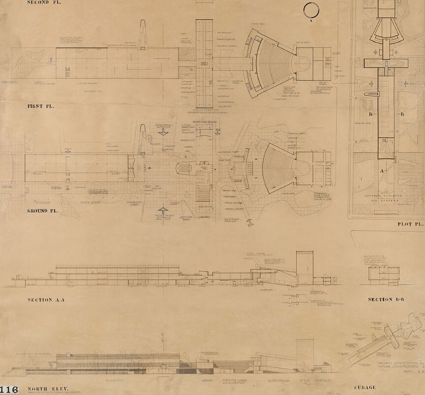
The image appears to be a set of architectural blueprints. There are several floor plans, cross-sections, and elevation drawings which indicate the design of a building. The plans include labels such as "SECOND FL.," "FIRST FL.," and "GROUND FL.," which suggest the layout of the building across multiple levels. There's also a detail labeled "NORTH ELEV.," which is likely the north-facing exterior view of the structure. The blueprints show a variety of rooms and spaces with detailed dimensions and sometimes indications of the purpose of the space, such as "AUDITORIUM." The craftsmanship in the drawing indicates a professional quality with precise lines and annotations, typical of architectural plans meant for construction use. The numbers and text are all aligned with architectural conventions, such as indicating the scale of the drawing and specific notes on materials or construction methods. The paper appears aged, with discoloration that suggests it could be an older document, and there's a number "116" in a bold font in the bottom left corner, which might refer to a page or sheet number within a larger set of plans.
Created by gpt-4o-2024-05-13 on 2025-03-06
This image is a detailed architectural plan drawing for a building, likely an educational or institutional structure given the labeled rooms and arrangement. The drawing is laid out on a large sheet and contains multiple sections, elevations, and floor plans: 1. **Floor Plans:** - **Second Floor Plan:** Shows the layout for the upper level including areas like exhibition spaces. - **First Floor Plan:** Details the main level with various rooms and pathways. - **Ground Floor Plan:** Depicts the base level including entranceways and foundational layout. 2. **Sections:** - **Section A-A:** A cross-sectional view detailing the vertical dimension and internal structure from one particular slice of the building. - **Section B-B:** Another cross-sectional view that provides a different perspective on the building’s internal layout. 3. **Elevations:** - **North Elevation:** A side view of the building's exterior, showing the facade and height details relative to the ground. 4. **Additional Details:** - **Plot Plan:** Shows the overall footprint of the building within its plot of land, giving context to the surrounding environment. - Various annotations and labels identify specific rooms and features such as the auditorium, administrative offices, and other functional spaces. - Measurements and technical notes are included to guide construction and ensure accuracy in translating this plan into a physical structure. The drawing has a professional and technical appearance, typically used by architects and builders to convey precise details necessary for constructing the building as designed.
Anthropic Claude
Created by claude-3-haiku-20240307 on 2024-12-30
This image appears to be an architectural blueprint or technical drawing, featuring detailed plans and elevations of a structure. The drawing includes multiple views of the building, including ground, first, and second floor plans, as well as section views and an elevation. The plans seem to be quite comprehensive, depicting the layout, dimensions, and various components of the structure. This type of technical drawing is often used by architects, engineers, or construction professionals to document and communicate the design details of a building project.
Created by claude-3-opus-20240229 on 2024-12-30
The image shows an architectural blueprint or floor plan for what appears to be a multi-story building, likely a theater or auditorium based on the labels. The plans depict different levels, including the "Ground Fl.", "First Fl.", "Second Fl.", and "Plot Pl." or plot plan. Various rooms, seating areas, stages, and architectural details are outlined in technical drawing style with measurements and annotations. Sections labeled "A-A" and "B-B" provide cross-sectional views revealing the interior structure and elevations. The aged paper and drawing style suggest these are vintage blueprints, carefully documenting the layout and design of a substantial building project.
Created by claude-3-5-sonnet-20241022 on 2024-12-30
This appears to be an architectural drawing or blueprint showing various floor plans, sections, and elevations of what looks like a theater or auditorium complex. The drawing includes: 1. Multiple floor plans labeled as "GROUND FL.", "FIRST FL.", and "SECOND FL." 2. A "PLOT PL." showing the site layout 3. Two section views labeled "SECTION A-A" and "SECTION B-B" 4. A north elevation view at the bottom of the drawing The most distinctive feature is a fan-shaped or semicircular area that appears to be an auditorium or theater space, visible in multiple floor plans. The building appears to have a long rectangular wing connected to this theater space. The drawings are quite detailed, showing structural elements, circulation spaces, and various room layouts. The drawing is done in a technical architectural style with fine lines and detailed annotations, though some appear faded due to the age of the document. The paper has a sepia or aged tone to it, suggesting this is a historical architectural document.
Meta Llama
Created by us.meta.llama3-2-11b-instruct-v1:0 on 2025-03-12
The image presents a detailed architectural plan for a building, showcasing various sections and elevations. The plan is divided into distinct sections, each labeled with its corresponding name. * **Section A-A** + Located at the bottom of the image + Features a cross-sectional view of the building + Includes labels for different components, such as the "ADMIN," "LIBRARY," and "AUDITORIUM" * **Section B-B** + Positioned to the right of Section A-A + Displays a side elevation of the building + Includes labels for the "ADMIN," "LIBRARY," and "AUDITORIUM" * **North Elevation** + Situated at the bottom of the image + Provides a front view of the building + Includes labels for the "ADMIN," "LIBRARY," and "AUDITORIUM" * **Cubage** + Located at the bottom-right corner of the image + Presents a detailed breakdown of the building's dimensions and measurements + Includes labels for the "TOTAL" and "FUTURE CONSTRUCTION" * **Plot Plan** + Occupies the top-right corner of the image + Features a top-down view of the building's layout + Includes labels for different areas, such as the "ADMIN," "LIBRARY," and "AUDITORIUM" The image provides a comprehensive overview of the building's design and layout, highlighting its various sections and elevations. The inclusion of labels and measurements adds to the detail and precision of the plan. Overall, the image appears to be a detailed architectural plan for a building, likely created for construction or renovation purposes.
Created by us.meta.llama3-2-90b-instruct-v1:0 on 2025-03-12
The image presents a comprehensive architectural blueprint, showcasing the detailed design of a building's layout. The blueprint is divided into sections, each labeled with a specific floor or area, including "SECOND FL.", "FIRST FL.", "GROUND FL.", and "SECTION A-A" and "SECTION B-B". These sections provide a clear visual representation of the building's structure and organization. The blueprint features a range of architectural elements, including walls, doors, windows, and staircases, which are meticulously drawn to scale. The use of lines, symbols, and annotations provides additional information about the building's design and functionality. The overall layout of the blueprint suggests that it is a working document, intended for use by architects, engineers, and contractors during the construction process. In the top-right corner of the image, the letters "SM" are visible, accompanied by the number "59". This notation may indicate the project number or a reference code for the blueprint. In the bottom-left corner, the number "116" is displayed, which could represent the page number or a section identifier. The background of the image appears to be a light brown or beige color, which is consistent with the traditional appearance of architectural blueprints. The overall aesthetic of the image suggests that it is a historical or vintage document, possibly dating back to the mid-20th century. In summary, the image presents a detailed architectural blueprint that showcases the design and layout of a building. The blueprint is divided into sections, features a range of architectural elements, and includes notations and annotations that provide additional information about the project. The image's aesthetic and content suggest that it is a historical or vintage document, likely created during the mid-20th century.
Amazon Nova
Created by amazon.nova-lite-v1:0 on 2025-01-12
The image is an architectural blueprint of a building. It features multiple sections and perspectives, including floor plans and elevations. The blueprint is labeled with various sections such as "SECOND FL." (Second Floor), "FIRST FL." (First Floor), "GROUND FL." (Ground Floor), "PLOT PL." (Plot Plan), "SECTION A-A", and "SECTION B-B". Each section provides detailed drawings of the building's layout, including rooms, corridors, and structural elements. The blueprint also includes notes and measurements, indicating dimensions and specific architectural features. The overall design appears modern and well-organized, with clear labeling and annotations.
Created by amazon.nova-pro-v1:0 on 2025-01-12
The image is a detailed architectural blueprint of a building. It is divided into multiple sections, each labeled with floor levels and specific areas such as "SECOND FL.", "FIRST FL.", and "GROUND FL." Additionally, there are sections labeled "SECTION A-A" and "SECTION B-B," which provide cross-sectional views of the structure. The blueprint includes various dimensions, measurements, and annotations that describe the layout, dimensions, and structural elements of the building. The document also includes a plot plan labeled "PLOT PL." which shows the building's position relative to the surrounding area. The blueprint is marked with the number "116" in the bottom left corner, indicating it is part of a series or a specific set of plans. The overall design appears to be for a multi-story building with detailed floor plans and structural sections.
Text analysis
Amazon