Machine Generated Data
Tags
Color Analysis
Categories
Imagga
| text visuals | 100% | |
Captions
Microsoft
created on 2018-03-23
| a close up of text on a whiteboard | 67.4% | |
| a close up of a whiteboard | 64.9% | |
| close up of text on a whiteboard | 63.9% | |
OpenAI GPT
Created by gpt-4 on 2025-03-06
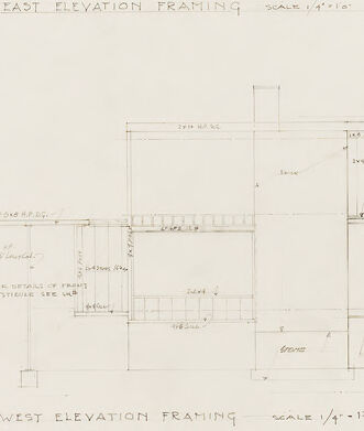
The image is of architectural drawings, specifically framing elevation plans for a building. There are two main drawings aligned horizontally - the top one is labeled "EAST ELEVATION FRAMING SCALE 1/4"=1'-0"" and the bottom one is labeled "WEST ELEVATION FRAMING SCALE 1/4"=1'-0"". Each drawing comprises several vertical and horizontal lines that represent the framework of building walls, along with various notations and dimensions indicating the sizes and distances between elements of the structure. The details include labels for different parts of the building, such as "Lintels," "2nd Floor," and "Beam," among others. There are also some smaller detail drawings with further specifications. The pencil or pen lines are precise and neat, demonstrating the careful planning that goes into drafting architectural plans. The paper appears aged with some discoloration and crease marks, indicating it might be an older document. There are some minor tears and tape at the top of the drawing, suggesting it has been handled and possibly repaired.
Created by gpt-4o-2024-05-13 on 2025-03-06
This image features an architectural drawing with two elevations labeled "East Elevation Framing" and "West Elevation Framing." Both elevations are drawn to a scale of 1/4 inch equals 1 foot, as indicated by the notes on the drawings. The drawings include detailed notations and measurements that outline the framing structure for the east and west sides of a building. These notations likely include dimensions, materials, and construction notes essential for understanding and building the structure's frame. The East Elevation Framing is displayed on the upper portion of the image, while the West Elevation Framing is on the lower portion. Both elevations show various structural elements, such as walls, floors, roofs, windows, and doors, each labeled with specific measurements and annotations about the construction details. The image overall has a technical and precise quality, characteristic of architectural plans, to guide builders in constructing the structure accurately.
Anthropic Claude
Created by claude-3-haiku-20240307 on 2024-12-30
The image appears to be a set of architectural drawings or plans. It shows the east elevation and west elevation framing for a structure. The drawings contain various measurements, labels, and technical details that appear to be part of the construction or design plans for this building or structure. The image does not contain any human faces or identifiable individuals.
Created by claude-3-opus-20240229 on 2024-12-30
The image shows architectural drawings or blueprints for the east and west elevations of a building, likely a house based on the residential-looking floor plan and room labels. The drawings include various measurements and annotations indicating wall heights, roof slopes, window and door placements, and different rooms and spaces within the structure, such as a garage, living room, kitchen, etc. The plans appear hand-drawn in pencil or pen on white or aged paper.
Created by claude-3-5-sonnet-20241022 on 2024-12-30
This image shows architectural drawings of east and west elevation framing plans. The drawings are technical in nature, rendered in a simple line drawing style typical of construction documents. Both elevations are drawn to a scale of 1/4"=1'-0" as noted on the drawings. The top drawing shows the east elevation framing, while the bottom shows the west elevation framing. They appear to be structural drawings showing the framework and support elements of a building, with various dimensions and notations marked throughout. The drawings include details of different levels and structural elements like beams and supports. The sketches are done in a clean, professional drafting style with thin lines on what appears to be paper that has slightly yellowed with age. There are some handwritten notes and dimensions scattered throughout both elevation views. The overall composition is typical of architectural construction documents used to guide builders in the framing process of a structure.
Meta Llama
Created by us.meta.llama3-2-11b-instruct-v1:0 on 2025-03-13
The image presents a hand-drawn architectural plan, featuring two sections: "EAST ELEVATION FRAMING" and "WEST ELEVATION FRAMING." The plan is drawn on white paper with pencil, showcasing the building's layout and framing details. **Key Features:** * **EAST ELEVATION FRAMING:** * The section is located at the top of the image. * It displays the eastern elevation of the building, including windows, doors, and other architectural features. * The drawing is detailed, with measurements and labels indicating the location and size of each element. * **WEST ELEVATION FRAMING:** * The section is situated at the bottom of the image. * It illustrates the western elevation of the building, featuring similar architectural elements as the eastern elevation. * The drawing is equally detailed, with measurements and labels providing clarity on the layout. * **Scale:** * The scale of the drawing is 1/4" = 1'-0". * This scale allows for precise measurements and calculations. * **Labels and Measurements:** * The drawing includes various labels and measurements, such as room numbers, door and window sizes, and other relevant details. * These labels and measurements are crucial for understanding the building's layout and design. * **Overall Impression:** * The hand-drawn plan exudes a sense of care and attention to detail. * The use of pencil and the inclusion of labels and measurements suggest a thoughtful and deliberate approach to the design process. In summary, the image presents a detailed and well-organized architectural plan, showcasing the building's layout and framing details. The use of pencil and the inclusion of labels and measurements demonstrate a commitment to precision and clarity in the design process.
Created by us.meta.llama3-2-90b-instruct-v1:0 on 2025-03-13
The image presents a technical drawing of a building's elevation, featuring two distinct sections: the east elevation framing and the west elevation framing. The drawings are rendered in pencil on a white background, with the title "EAST ELEVATION FRAMING" and "WEST ELEVATION FRAMING" written in pencil below each respective section. **Key Features:** * **East Elevation Framing:** This section is situated at the top of the image and provides a detailed view of the building's east-facing side. It includes various architectural elements such as windows, doors, and rooflines. * **West Elevation Framing:** Located at the bottom of the image, this section offers a comprehensive look at the building's west-facing side. Similar to the east elevation, it features an array of architectural components like windows, doors, and rooflines. * **Scale:** Both sections are drawn to a scale of 1/4" = 1'-0", indicating that every quarter inch on the drawing represents one foot in real life. * **Annotations:** Throughout the drawings, there are numerous annotations and notes written in pencil. These annotations likely provide additional information about the design, materials, or construction details. * **Background:** The background of the image is a plain white surface, which helps to focus attention on the technical drawings. **Conclusion:** In summary, the image showcases a detailed technical drawing of a building's elevation, divided into two sections: the east elevation framing and the west elevation framing. The drawings are meticulously rendered in pencil and feature various architectural elements, annotations, and a clear scale. The plain white background effectively highlights the technical aspects of the design, making it an informative and useful resource for architects, builders, or anyone interested in the construction process.
Amazon Nova
Created by amazon.nova-lite-v1:0 on 2025-01-12
The image shows a blueprint of a house with two elevations, the east and west. The blueprint is labeled as "EAST ELEVATION FRAMING" and "WEST ELEVATION FRAMING" with a scale of 1/4" = 1'-0". The blueprint includes the dimensions of the house, the type of materials used, and the location of the windows and doors. The blueprint also includes the details of the foundation, the type of flooring, and the type of roofing. The blueprint is a technical drawing that provides detailed information about the construction of the house.
Created by amazon.nova-pro-v1:0 on 2025-01-12
The image is a technical drawing of a building's structural framing, specifically detailing the east and west elevation framing. The drawing is presented on a white background and includes two main sections labeled "EAST ELEVATION FRAMING" and "WEST ELEVATION FRAMING." Each section contains detailed architectural blueprints that illustrate the layout of the structural components, such as beams, columns, and other framing elements. The drawing includes annotations, measurements, and notes that provide specific instructions and details about the construction. The scale of the drawing is indicated as 1/4"=1'-0", meaning that every quarter inch on the drawing represents one foot in actual construction. The overall design appears to be for a multi-story building, with various levels of framing depicted.
Text analysis
Amazon