Machine Generated Data
Tags
Color Analysis
Categories
Imagga
| text visuals | 99.7% | |
Captions
Microsoft
created on 2019-07-30
| a close up of a sign | 70.2% | |
| close up of a sign | 65.4% | |
| a sign on a wall | 51.8% | |
OpenAI GPT
Created by gpt-4 on 2025-03-08
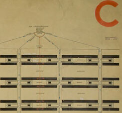
You provided an image of a detailed architectural or engineering plan. The plan features several technical drawings spread across the canvas. On the left side, there is a linear arrangement with rectangles and interconnected lines, possibly representing a floor plan or an electrical/circuit diagram with annotations indicating dimensions and probably functional areas. The center of the image contains a more complex diagram with numerous interconnected boxes, which could be another aspect of the floor plan or a subsystem layout, featuring many vertical and horizontal lines that could correspond to structural elements, pathways, or conduits. On the right side, there's a different kind of schematics depicting a front-facing and a side view of a structure, which may be illustrating elevations of a building or a machine part. These views display horizontal lines across the vertical axis, suggesting different levels or components. The plans are marked with various symbols, notations, and some color-coded elements, which are standard practice in technical drawings to convey specific details to professionals like architects or engineers. The image has a cream-colored background, which suggests age or a style choice meant to resemble traditional drafting paper. In the top right corner, there's a large letter "C," which might be used for indexing or categorization purposes in a set of plans.
Created by gpt-4o-2024-05-13 on 2025-03-08
This image appears to be a technical architectural blueprint for a building or structure. The layout is displayed in a landscape orientation and consists of multiple views. 1. The left section shows a top-down floor plan, presenting a linear arrangement of rooms or spaces along a central corridor. 2. The middle section features a detailed blueprint with both a top-down view and a vertical cross-sectional view of the structure, providing insight into the layout and internal division of the building. 3. The right section has an elevation view, illustrating one of the exterior facades of the building, highlighting windows and structural elements. The color red is used sparingly, marking certain elements most noticeably with a large "C" in the top right corner. The overall design is drawn with precise lines and annotations, typical of an architectural plan. The parchment is aged and has a yellowish tint, indicating that it might be an older document.
Anthropic Claude
Created by claude-3-haiku-20240307 on 2025-01-21
The image appears to be an architectural floor plan or blueprint. It contains detailed technical drawings and diagrams, including floor layouts, elevations, and other structural elements. The plan seems to be for a larger building or complex, with multiple sections and levels indicated. The overall design appears to be functional and practical, without any human figures or identifiable elements.
Created by claude-3-5-sonnet-20241022 on 2025-01-21
This is an architectural drawing or blueprint showing different views of what appears to be a multi-unit building design. The drawing includes a floor plan view (left), a cross-sectional view (middle), and an elevation view (right). The floor plan shows a long corridor-style building with multiple rooms arranged in a linear fashion on both sides of a central hallway. There's a curved element at one of the junctions. The cross-section reveals the building's internal structure across multiple floors, while the elevation view shows the exterior facade with a regular pattern of windows and architectural elements. The drawing is rendered in a technical style typical of architectural plans, with clean lines on what appears to be aged paper. There's a "C" marking in the top right corner of the document, suggesting this might be part of a larger set of architectural drawings.
Created by claude-3-opus-20240229 on 2025-01-21
The image shows an architectural plan or blueprint drawn on aged paper. It contains floor plan layouts and elevations of a multi-story building, likely some type of apartment complex or dormitory based on the repetitive, modular room layouts. The plans depict the arrangement of individual residential units along central corridors on each floor. Various annotations, dimensions and reference markers are included to specify architectural details and measurements. A legend or key in the bottom right associates letters like "C" with particular building elements or material designations. The yellowed appearance and faded red markings on the blueprint suggest it is an older, vintage architectural drawing, perhaps from the early-to-mid 20th century based on the style and rendering technique. Overall, it provides a fascinating glimpse into the technical planning and design process behind a large residential building project from the past.
Meta Llama
Created by us.meta.llama3-2-90b-instruct-v1:0 on 2025-01-21
The image presents a vintage architectural blueprint, showcasing the design of a building. The blueprint is divided into three sections, each featuring a distinct view of the structure. **Left Section:** This section displays a top-down view of the building's layout, with various rooms and corridors visible. The design appears to be symmetrical, with identical wings on either side of a central axis. A series of small rectangles represents individual rooms, while larger rectangles denote common areas or hallways. A curved line connects two sections of the building, possibly indicating a staircase or elevator shaft. **Center Section:** This section provides a detailed view of the building's floor plan, highlighting the arrangement of rooms and corridors. The design features a mix of rectangular and square rooms, with some areas appearing to be open spaces or common areas. A series of lines and symbols indicate the location of doors, windows, and other architectural features. **Right Section:** This section shows a cross-sectional view of the building, revealing its vertical structure. The design features multiple levels, with each level comprising a series of rectangular rooms and corridors. A series of lines and symbols indicate the location of stairs, elevators, and other vertical circulation elements. **Additional Features:** The blueprint includes several additional features, such as: * A red "C" in the top-right corner, which may indicate the building's classification or category. * A series of numbers and letters along the edges of the blueprint, which may represent the building's dimensions or other technical information. * A faint grid pattern visible in the background, which may be used to scale the design or ensure accuracy. Overall, the image provides a detailed and informative view of the building's design, showcasing its layout, structure, and architectural features.
Created by us.meta.llama3-2-11b-instruct-v1:0 on 2025-01-21
The image presents a detailed architectural plan for a building, showcasing its layout and design. The plan is rendered in black ink on a yellowed paper background, with various elements and features highlighted in red. **Key Features:** * **Building Layout:** The plan depicts the building's floor plan, including the location of rooms, corridors, and other spaces. * **Room Designations:** Each room is labeled with a number or letter, indicating its purpose or function. * **Corridor and Stairwell:** A corridor runs along the center of the building, connecting the various rooms and spaces. A stairwell is also visible, providing access to the upper floors. * **Red Highlights:** Certain features, such as doors, windows, and electrical outlets, are highlighted in red to draw attention to their location and importance. * **Scale and Measurements:** The plan includes a scale and measurements, allowing architects and builders to accurately interpret the design and construct the building. * **Overall Design:** The building's design appears to be functional and efficient, with a focus on maximizing space and minimizing unnecessary features. **Conclusion:** The architectural plan provides a comprehensive overview of the building's design and layout, highlighting its key features and functional elements. The use of red highlights and clear labeling makes it easy to navigate and understand the plan, making it a valuable tool for architects, builders, and anyone interested in the building's design.
Amazon Nova
Created by amazon.nova-pro-v1:0 on 2025-01-21
The image shows a large architectural drawing with three different floor plans on it. The drawing is in black and white and is on a beige-colored piece of paper. The drawing is on the right side of the paper, and there is a red "C" in the top right corner. The paper also has a black border around it. The drawing is of a building with multiple floors and windows.
Created by amazon.nova-lite-v1:0 on 2025-01-21
The image appears to be an architectural blueprint or floor plan of a building. The blueprint is printed on a light brown or beige paper and is divided into three sections, each labeled with a letter (A, B, and C) in the upper right corner. The blueprint shows a detailed layout of the building's floor plan, with various rooms and spaces marked out. The sections labeled A and B show the ground floor plan, while the section labeled C shows a cross-sectional view of the building. The blueprint also includes measurements and annotations in the upper left corner, indicating the scale and dimensions of the building. Overall, the blueprint provides a detailed and comprehensive view of the building's layout and design.
Text analysis
Amazon