Machine Generated Data
Tags
Color Analysis
Categories
Imagga
| text visuals | 99.8% | |
Captions
Microsoft
created on 2020-04-27
| a clock mounted to the side | 71.4% | |
| a clock hanging on the wall | 59.2% | |
| a large clock mounted to the side | 59.1% | |
OpenAI GPT
Created by gpt-4 on 2025-03-05
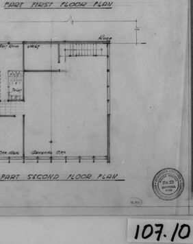
The image displays an architectural drawing or blueprint featuring the floor plans for two levels of a building, labeled "Fort First Floor Plan" and "Fort Second Floor Plan." The plans show various rooms and spaces within the building, each labeled with its intended use, such as "Dining Room," "Kitchen," "Living Room," etc. The layout includes measurements for different sections of the rooms, indicating that this is a precise technical drawing used for construction or architectural purposes. The drawing is encased in a black border, and there is a scale notation indicating "Scale 1/4" = 1'0"" which specifies the scale at which the drawing was made. On the bottom right corner, there's a number "107.10" which could be a reference number for the drawing, and a round stamp from an official entity, often indicating approval or certification of the architectural plan. The edges of the drawing are worn, and there's a visible rod on the right side, suggesting that this blueprint might be part of a larger set or archive of plans.
Created by gpt-4o-2024-05-13 on 2025-03-05
The image is a photograph of an architectural drawing. It appears to be a black-and-white floor plan that includes two sections: "Part First Floor Plan" at the top and "Part Second Floor Plan" below it. The floor plans denote various rooms and spaces within a building layout, with measurements and labels for different areas. The drawing is encased within a rectangular frame and has a scale indication of "1/8" = 1'0"" at the bottom of the image. There is also a circular stamp that might be an approval or reference mark, and a smaller rectangular boxed area at the bottom right with the number "107.10" written inside it, possibly indicating a reference code or document number. A ruler is placed vertically on the right side of the image.
Anthropic Claude
Created by claude-3-5-sonnet-20241022 on 2025-01-14
This is an architectural floor plan drawing showing both the first and second floor layouts of what appears to be a commercial or institutional building. The drawing is in black and white and appears to be a historical document, labeled "107.10". The first floor plan shows a large open space with stairwells and smaller rooms positioned around the perimeter. The second floor plan reveals more compartmentalized spaces, including what appear to be offices and meeting rooms, with stairwell access points. The plans are drawn to scale and include detailed measurements and room labels. The style and presentation suggests this is likely a professional architectural drawing from an earlier era, possibly mid-20th century based on the drawing techniques and formatting.
Created by claude-3-opus-20240229 on 2025-01-14
The image shows an architectural floor plan sketch drawn on paper or vellum. It depicts the layout of what appears to be a single floor of a building, with various rooms and spaces delineated by thin lines. Dimensions and measurements are annotated on the plan. The floor plan has two main sections - one labeled "First Floor Plan" and the other "Part Second Floor Plan", suggesting it covers multiple levels. Rooms are labeled with their sizes and some have additional labels like "Toilet" and "Coat Closet". The sketch has a rough, hand-drawn quality with some areas of shading added for emphasis or to indicate walls or solid elements. A scale ruler or straight edge is visible along the bottom edge of the drawing. Overall, this looks to be an early schematic floor plan sketch, likely done by an architect in the initial stages of designing or documenting a building layout. The style and lettering has an vintage quality, so this may be an older architectural drawing.
Created by claude-3-haiku-20240307 on 2025-01-14
This image appears to be architectural floor plans for a building. The plans show the layouts of the first and second floors, with various rooms and spaces labeled. The plans are drawn in a technical, schematic style, with measurements and dimensions provided. This type of image is commonly used by architects, engineers, and construction professionals to visualize and plan the design and layout of a building.
Meta Llama
Created by us.meta.llama3-2-90b-instruct-v1:0 on 2025-01-14
The image presents a black-and-white photograph of a floor plan, likely for a building or house. The floor plan is divided into two sections: the first floor and the second floor. Each section features various rooms, including a living room, dining room, kitchen, bedrooms, and bathrooms. The rooms are labeled with their respective names, and the floor plan also includes measurements and other details. In the bottom-right corner of the image, there is a small circular logo or stamp that appears to be a seal or certification mark. Below this logo, the number "107.10" is handwritten in black ink. The background of the image is a light gray color, which suggests that it may have been scanned or photographed from an original document or blueprint. Overall, the image provides a detailed and informative view of the floor plan, allowing viewers to visualize the layout and design of the building or house.
Created by us.meta.llama3-2-11b-instruct-v1:0 on 2025-01-14
The image presents a black-and-white floor plan of a building, likely a house or office space, with two distinct levels. The top level is designated as the "Port First Floor Plan" and features several rooms, including a living room, dining room, kitchen, and bedrooms. The bottom level is labeled as the "Port Second Floor Plan" and includes additional rooms such as a bathroom, closet, and storage area. **Key Features:** * **Port First Floor Plan:** + Living room + Dining room + Kitchen + Bedrooms * **Port Second Floor Plan:** + Bathroom + Closet + Storage area **Additional Elements:** * A ruler is placed on the right side of the image. * A circular logo is visible in the bottom-right corner. * A handwritten note in the bottom-right corner reads "107.10". **Background:** * The floor plan is set against a light-colored background. * A dark border surrounds the image. **Overall:** The image provides a detailed view of the building's layout, showcasing the various rooms and spaces within each level. The inclusion of a ruler and logo suggests that this may be a technical or architectural drawing.
Amazon Nova
Created by amazon.nova-pro-v1:0 on 2025-01-14
The image is a photograph of a blueprint of a building's floor plan. It shows two separate floor plans, each on a different floor of the building. The blueprint is detailed, showing the layout of rooms, corridors, and other features. The top floor plan is labeled as "First Floor Plan," and the bottom floor plan is labeled as "Second Floor Plan." The blueprint includes measurements, room labels, and other annotations. The image is framed in a black border, and there is a ruler on the right side for scale. The blueprint appears to be a professional architectural drawing, likely used for construction or renovation purposes.
Created by amazon.nova-lite-v1:0 on 2025-01-14
This image is a black-and-white architectural blueprint, likely from a historical document, depicting two floor plans of a building. The blueprint is labeled "107.10" at the bottom right corner. The top section of the blueprint is titled "MOST FIRST FLOOR PLAN," while the bottom section is titled "PART SECOND FLOOR PLAN." The blueprint features a grid-like structure with various rooms and areas marked, including "Lounge Room," "Bath," "Plant Room," "Stores," "Canteen," "General Office," and "Drawing Office." The blueprint also includes measurements and dimensions for each room and area, providing a detailed layout of the building's interior spaces.
Created by amazon.nova-lite-v1:0 on 2025-01-10
The image is a black-and-white architectural floor plan drawing. It appears to be a blueprint or technical drawing, commonly used in construction and architectural design. The floor plan shows two distinct sections: the "Most First Floor Plan" and the "Part Second Floor Plan." Each section is labeled and separated by a horizontal line. The drawing includes various rooms and spaces, with dimensions and labels indicating their sizes and functions. The scale of the drawing is mentioned as "Scale 1/8"=1'-0". The drawing also includes a stamp or seal in the bottom right corner, possibly indicating the architect or designer responsible for the plan.
Created by amazon.nova-pro-v1:0 on 2025-01-10
The image is a black-and-white architectural blueprint of a building, specifically showing the floor plans for the first and second floors. The blueprint is framed by a black border and includes a scale ruler on the right side for reference. The plans are labeled "FIRST FLOOR PLAN" and "PART SECOND FLOOR PLAN," indicating the two levels depicted. The first floor plan shows a layout with various rooms and spaces, including a large central area that could be a living room or common space, surrounded by smaller rooms that may serve as bedrooms, bathrooms, or utility spaces. The rooms are labeled with numbers and descriptions, such as "Bedroom," "Bathroom," and "Kitchen." The second floor plan appears to have a similar layout, with a large central space and several smaller rooms. The rooms on this floor are also labeled with numbers and descriptions, suggesting a continuation of the living spaces from the first floor. The blueprint includes a grid system for precise measurements and dimensions, allowing for accurate construction and planning. The scale ruler on the right side provides a reference for the actual size of the rooms and spaces depicted in the plan. Overall, the image represents a detailed architectural blueprint for a residential building, showing the floor plans for the first and second floors with labeled rooms and precise measurements.
Text analysis
Amazon