Machine Generated Data
Tags
Color Analysis
Feature analysis
Amazon
Clarifai

Clarifai
| Whiteboard | 44.2% | |
Categories
Imagga
created on 2018-03-23
| text visuals | 99.9% | |
| paintings art | 0.1% | |
Captions
Microsoft
created by unknown on 2018-03-23
| a close up of text on a white surface | 63.1% | |
| a close up of text on a white background | 62.8% | |
| a close up of text on a black surface | 62.7% | |
Clarifai
No captions written
Salesforce
Created by general-english-image-caption-blip on 2025-05-02
a photograph of a drawing of a plan for a house
Created by general-english-image-caption-blip-2 on 2025-06-28
two plans of a house and a drawing of the interior
OpenAI GPT
Created by gpt-4 on 2025-03-07
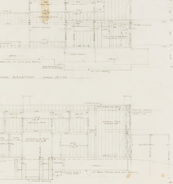
The image shows an architectural drawing with multiple elevation views of a building. The drawings appear to be hand-drawn in pencil, with annotations and dimensions provided. The image includes a "South (Rear) Elevation" and a "North (Front) Elevation" with scales noted as 1/4" = 1'-0". The drawings feature various detailed components of the building's design, such as windows, doors, and walls, and include measurements for these elements.
The paper itself appears aged, with some discoloration and stains, suggesting the drawing might be quite old or has been exposed to elements that have caused some wear. There is meticulous attention to detail in the representation of the building's structure, which is typical for architectural blueprints and elevation plans.
Created by gpt-4o-2024-05-13 on 2025-03-07
The image shows a technical drawing of a building's architectural plans. It includes detailed elevation views from the south (rear) and north (front) sides along with framing details. The drawing includes numerous measurements and annotations, indicating the dimensions and structural elements of the building. The south elevation is drawn to a scale of 1/4 inch to 1 foot, and the north elevation framing is scaled at 1/4 inch to 1 foot. The drawing appears to be hand-drawn with precise lines and text, typical of architectural blueprints used for construction planning. Various components like windows, doors, and structural supports are labeled, providing a detailed representation of the building's exterior and structural design. The drawing also shows gridlines and reference markers to ensure accuracy.
Anthropic Claude
Created by us.anthropic.claude-3-5-sonnet-20241022-v2:0 on 2025-06-24
This image shows architectural elevation drawings of a building's north and south faces. The drawings are technical in nature, showing the framing and structural details at a scale of 1/4"=1'0". The elevations include detailed measurements and notations for various building elements like walls, openings, and structural components. The top drawing is labeled "SOUTH (REAR) ELEVATION" while the bottom drawing is labeled "NORTH (FRONT) ELEVATION FRAMING". The drawings appear to be done in pencil on paper and include various construction notes and dimensional markings throughout. These are typical working drawings that would be used during the construction process to guide builders on the proper assembly and dimensions of the structure.
Created by claude-3-haiku-20240307 on 2024-12-31
The image appears to be an architectural drawing or blueprint, featuring a south elevation and a north (front) elevation of a building or structure. The drawing is primarily composed of technical details, measurements, and annotations, with no visible human figures. It appears to be a technical document, likely used for construction or planning purposes.
Created by claude-3-opus-20240229 on 2024-12-31
The image shows architectural drawings of building elevations. The drawings depict the front (south) and rear (north) facades of a structure, with various measurements and annotations marked on the plans. Based on the title, these appear to be elevation framing plans drawn to a scale of 1/4" = 1'-0". The plans show the layout and dimensions of structural framing elements like walls, windows, doors and roof lines. The drawings have a grid overlay and are done in a technical drafting style on aged paper, suggesting they may be original hand-drawn architectural plans for a building project.
Created by claude-3-5-sonnet-20241022 on 2024-12-31
This image shows architectural elevation drawings of a building's south and north faces. It appears to be a technical architectural drawing done to scale (1/4" = 1'0"), showing the framing and structural details of the building. The drawings include dimensions, notations, and construction details.
The top drawing is labeled "SOUTH LEGAL ELEVATION" and the bottom drawing is labeled "NORTH (FRONT) ELEVATION FRAMING." Both elevations show a multi-level structure with various framing members, openings, and structural elements clearly delineated. The drawings are done in a professional architectural style with clean lines and precise measurements noted throughout.
The drawings appear to be vintage or historical, given the hand-drawn nature and slight yellowing/aging of the paper. They provide detailed information about the building's construction and would have been used as part of the building's construction documents.
Meta Llama
Created by us.meta.llama3-2-11b-instruct-v1:0 on 2025-03-13
The image presents a detailed architectural blueprint, comprising two floor plans and an elevation drawing. The blueprint is rendered in pencil on a white background, with a faint yellow stain visible in the top center.
Floor Plans:
- The top floor plan is labeled "SOUTH (REAR) ELEVATION" and features a rectangular shape with various rooms and hallways.
- The bottom floor plan is labeled "NORTH (FRONT) ELEVATION FRAMING" and appears to be a more detailed view of the building's framing structure.
Elevation Drawing:
- The elevation drawing is situated between the two floor plans and provides a side view of the building's exterior.
Additional Details:
- Various measurements and notes are scattered throughout the blueprint, likely indicating specific dimensions and construction requirements.
- The overall design of the building appears to be a single-story structure with a rectangular footprint.
Conclusion:
The blueprint provides a comprehensive visual representation of the building's design, allowing architects, engineers, and contractors to accurately plan and construct the project. The inclusion of detailed measurements and notes ensures that the final product meets the desired specifications and standards.
Created by us.meta.llama3-2-90b-instruct-v1:0 on 2025-03-13
The image depicts a technical drawing of a building's elevation and framing, likely created by an architect or engineer. The drawing is divided into two sections: the top section shows the south rear elevation, while the bottom section displays the north (front) elevation framing.
Key Features:
- Elevation Drawings: The top section features a detailed drawing of the south rear elevation, including measurements and labels for various components such as windows, doors, and rooflines.
- Framing Details: The bottom section provides a detailed view of the north (front) elevation framing, showcasing the structural elements that support the building's exterior walls and roof.
- Scale and Measurements: The drawing includes a scale indicator, allowing viewers to accurately measure distances and dimensions within the design.
- Handwritten Notes: Throughout the drawing, handwritten notes and annotations provide additional information about the design, including materials, construction methods, and other relevant details.
Overall Impression:
This technical drawing appears to be a working document used during the design and construction process. It provides a detailed and accurate representation of the building's elevation and framing, allowing architects, engineers, and contractors to plan and execute the project effectively.
Amazon Nova
Created by amazon.nova-lite-v1:0 on 2025-02-26
The image is a technical architectural drawing of a building's structural design. It is divided into two sections, each with a title and scale. The top section is titled "SOUTH (REAR) ELEVATION" and the bottom section is titled "NORTH (FRONT) ELEVATION FRAMING." The scale is indicated as 1/4" = 1'-0" for both sections. The drawing features detailed lines and measurements, indicating the layout of the building's structure, including the framing, joists, and other structural components. The drawing is on a white background with black lines and measurements, and it appears to be a technical document used for construction or engineering purposes.
Created by amazon.nova-pro-v1:0 on 2025-02-26
The image depicts two architectural drawings of a building. The top drawing is labeled "SOUTH (REAR) ELEVATION," and the bottom drawing is labeled "NORTH (FRONT) ELEVATION." Both drawings show the elevation and framing of the building, with dimensions and measurements provided. The top drawing shows the rear elevation of the building, while the bottom drawing shows the front elevation. The drawings are in black and white and appear to be from an older architectural plan.
Google Gemini
Created by gemini-2.0-flash on 2025-05-12
Here is a description of the image:
The image shows two architectural drawings, one above the other, of what appears to be the rear and front elevations of a building's framing structure. Both drawings are rendered in a technical style, likely done by hand, with precise lines and measurements. The top drawing is labeled "SOUTH (REAR) ELEVATION" and has a scale of 1/4" = 1'0". The bottom drawing is labeled "NORTH (FRONT) ELEVATION FRAMING" with a scale of 1/4" = 1'0".
Both elevations depict the skeletal structure of the building, revealing the studs, sills, plates, and other structural members that make up the frame. Dimensions and notes are annotated on the drawings to provide specific information about the size and placement of the various elements.
The drawings give a detailed view of the building's framing, providing essential information for construction purposes.
Created by gemini-2.0-flash-lite on 2025-05-12
This is a technical drawing, most likely an architectural blueprint, showing two elevations of a building: the South (Rear) Elevation and the North (Front) Elevation. The drawing is a hand-drawn sketch, as evidenced by the ink lines and annotations. The scale is indicated as 1/4 inch equals 1 foot. The South (Rear) Elevation depicts the back of the building, and the North (Front) Elevation shows the front of the building, and it's labelled 'FRAMING.' Various structural elements are labelled, such as beams, studs, and plates. The annotations provide details about the materials and construction techniques to be used in the building. There is also a date included at the bottom right of the image "Review-Mar. 29/90".
Mistral Pixtral
Created by us.mistral.pixtral-large-2502-v1:0 on 2025-05-31
The image shows two detailed architectural elevation drawings of a building. These drawings are labeled as "SOUTH (REAR) ELEVATION" and "NORTH (FRONT) ELEVATION FRAMING." Both drawings are scaled at 1/4" = 1'-0".
South (Rear) Elevation:
- Dimensions and Layout: The drawing shows the rear facade of the building, including various structural elements such as walls, windows, and doors.
- Measurements: Specific dimensions are provided for the heights of walls, window placements, and door openings.
- Materials and Features: The drawing indicates the use of different materials and features such as siding, trim, and flashing.
- Annotations: There are notes and annotations indicating specific details such as "2x6 Wall," "2x4 Wall," "4x4 Post," and "2x6 Rafter."
North (Front) Elevation Framing:
- Dimensions and Layout: This drawing shows the front facade of the building, focusing on the framing structure.
- Measurements: Detailed measurements are provided for the heights of walls, window placements, and door openings.
- Materials and Features: The drawing specifies the use of framing members such as studs, headers, and beams.
- Annotations: There are notes and annotations indicating specific details such as "2x6 Wall," "2x4 Wall," "4x4 Post," and "2x6 Rafter."
General Observations:
- Scale: Both drawings are to scale, with 1/4 inch representing 1 foot.
- Purpose: These drawings are likely used for construction purposes, providing detailed information for builders on how to frame and construct the building's front and rear facades.
- Complexity: The drawings are highly detailed, including specific measurements and material specifications necessary for accurate construction.
These elevation drawings are essential for ensuring that the building is constructed according to the designed specifications, providing a clear visual representation of the structural elements and their dimensions.
Qwen
No captions written
Text analysis
Amazon