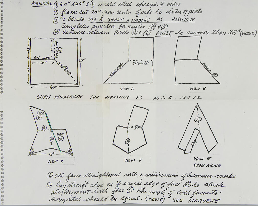
MATERIAL
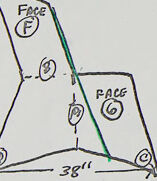
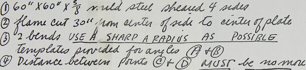
60" X60" X% nuld stul sheaud 4 sides
e flame
cut 30" m cintea forde to eintu gplate
O2 bends vsE A
templato pineded fn any leo
O Deštance betwein ponts @F MUST be no mn han 38"(uIewc)
SHARP A RAPI US
POSSIBLE
AS
cur LINE
30L
ANGLE
ANGLE@
VIEW A
VIEW B
CHRIS WILMARIH
144 WOOSTER
N. Y, C. /0012
57
FAÇE
FACE
3811
VIEW e
VIEW P
VIEW E
FROM ABOVE
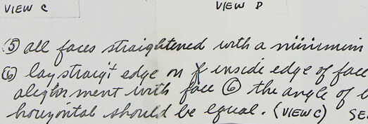
3 all facus stiaighitened unth a niniumnin fhamnur muks
O layotrayi edgem
alejonmint inih fill O the anyeg loth facco to
houzntal shruld be egual. (VIEW C) ° SEE MAQUETE
insede edge f face' Bto chech
ANGLE
DO000