Machine Generated Data
Tags
Color Analysis
Categories
Imagga
created on 2022-01-15
| text visuals | 100% | |
Captions
Microsoft
created by unknown on 2022-01-15
| diagram | 83% | |
Salesforce
Created by general-english-image-caption-blip on 2025-05-03
a photograph of a drawing of a diagram of a triangle
OpenAI GPT
Created by gpt-4o-2024-11-20 on 2025-06-12
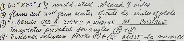
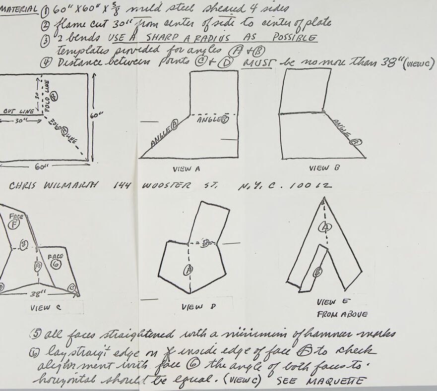
This image is a hand-drawn technical sketch or diagram with instructions for fabricating an object from steel. It appears to describe how to cut, bend, and assemble a steel plate into a specific shape. The drawing includes multiple views of the object, labeled "View A," "View B," "View C," "View D," and "View E from above." It is detailed with measurements, angles, and instructions for fabrication.
Here is a breakdown of the image:
Material Specification:
The top left specifies the material as "60"x60"x3/8" mild steel sheared 4 sides."Fabrication Steps:
- Flame cut 30” from the center of the plate to the edges.
- Add two bends, noting to "use a sharp radius as possible."
- Templates are provided for angles A and B.
- The distance between two points, referred to as "C+D," must not exceed 38 inches.
Drawings and Views:
- View A and B: These show side elevations with bends (angles) labeled at specific parts.
- View C: Displays additional faces labeled "F" and "G," pointing out dimensions and alignment.
- View D and E: Include a perspective from above and details about angles and orientations.
Additional Written Notes:
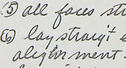
- Align all edges with minimal hammer marks.
- Straighten the edge and check alignment of angles on the finished piece.
- Reference to a maquette (model) to ensure accuracy.
At the bottom of the diagram, there is a name and address: “Chris Wilmarth, 144 Wooster St., NYC 10012,” indicating the designer or creator of this schematic. The diagram combines technical instructions with rough sketches for the construction of a steel object.
Created by gpt-4o-2024-08-06 on 2025-06-12
The image is a hand-drawn technical sketch with instructions for fabricating a metal component. It contains several views of the component and written instructions, indicating measurements and specific details for construction. The material specified is a 60" x 60" x 3/8" mild steel sheet, which is to be sheared on four sides. There are instructions to flame cut 30" from the center of the fold to the center of the plate and to make two bends using a sharp radius. A template is provided for the angles A and B, with a requirement that the distance between points C and D must be no more than 38" (view C).
The sketches include:
- A top view showing the layout of the cut line and dimensions.
- Side views labeled as View A and View B.
- A front view labeled as View C, indicating the position of faces F and G.
- An isometric view labeled as View P.
- A top view labeled as View G, showing an angle from above.
There are additional notes, indicating that all faces should be straightened with a minimum of hammer marks, and to lay a straight edge at the outside edge of face D to check alignment with face C, ensuring the angle of both faces to horizontal should be equal, referencing view C. The contact details at the bottom mention Chris Wilmarth, with an address at 144 Wooster St., N.Y.C. 10012.
Anthropic Claude
Created by anthropic.claude-3-haiku-20240307-v1:0 on 2025-06-20
The image appears to be a technical drawing or schematic with various measurements and instructions. It does not contain any human faces, so I will describe the contents of the image without identifying any individuals.
The drawing shows several different views and perspectives of a metal object or structure, including a front view, side view, and view from above. The measurements and notes provide details about the dimensions and construction of the object, such as the size, angle, and distance between different parts.
The text also includes instructions for the fabrication or assembly of the object, such as using a sharp radius, templating, and aligning the faces. There are also references to specific individuals, but I will not identify them by name.
Overall, this appears to be a technical document or plan related to the design and construction of a metal component or structure.
Created by us.anthropic.claude-3-5-sonnet-20241022-v2:0 on 2025-06-20
This image appears to be a technical drawing or blueprint with multiple views of what seems to be a metal fabrication project. The material specifications at the top indicate it's made from 60" x 60" x 7/8" mild steel sheeted 4 sides. The drawing includes several views (labeled View A through View E) showing different angles and perspectives of what appears to be a bent metal structure.
Key specifications include:
- A flame cut 30" from center of side to center of plate
- Instructions to use "AS SHARP A RADIUS AS POSSIBLE"
- A requirement that the distance between points must be no more than 38" (inside)
- Various views showing different angles and bends in the material
- A top-down view (View E)
The drawing is signed "CHRIS WILMARTH 144 WOOSTER ST. N.Y.C. 10012" and includes additional notes about straightening faces and checking alignments. The document appears to be on lined or graph paper and includes detailed measurements and specifications for fabrication.
Meta Llama
Created by us.meta.llama3-2-11b-instruct-v1:0 on 2025-06-10
The image presents a detailed, hand-drawn diagram on white paper, accompanied by handwritten notes. The diagram is divided into two sections: the top section features a series of sketches and measurements, while the bottom section provides additional notes and instructions.
Top Section:
- A large rectangle with dimensions labeled "60" x 60" x 5/8" mild steel sheet 4 sides"
- A smaller rectangle with dimensions labeled "30" x 30" x 1/4" flame cut 30" from center of each to enter of plate"
- A note stating "2 bends USE A SHARP A RADIUS AS POSSIBLE"
- A template provided for angles A and B
- A note indicating that distance between points C and D must be no more than 38" (view C)
Bottom Section:
- A series of sketches and measurements, including:
- A view of the object from above
- A view of the object from the side
- A view of the object from the front
- A view of the object from the back
- Additional notes and instructions, including:
- "all faces straightened with a minimum of hammer strokes"
- "lay straight edge on X inside edge of face B to check alignment"
- "the angle of both faces to horizontal should be equal"
Overall:
The diagram appears to be a technical drawing or blueprint for a metal object, likely a machine part or component. The handwritten notes and measurements suggest that the diagram is intended for use in a workshop or manufacturing setting, where precise measurements and attention to detail are crucial.
Created by us.meta.llama3-2-90b-instruct-v1:0 on 2025-06-10
The image depicts a handwritten note with sketches and instructions for creating a metal plate. The note is written in black ink on white paper, with a spiral binding visible along the left edge.
Title and Material
At the top of the page, the title "MATERIAL" is underlined, followed by a list of materials and dimensions:
- 60" x 60" x 3/8" mild steel sheared 4 sides
- Flame cut 30" from center of side to center of plate
- 1/2 bends USE A SHARP A RADIUS AS POSSIBLE
- Templates provided for angles A and B
- Distance between points A and B MUST be no more than 38"
Sketches and Views
Below the title, there are six sketches of the metal plate from different angles, labeled as follows:
- View A: A top-down view of the plate, showing the 30" flame cut and the 1/2 bends.
- View B: A side view of the plate, showing the angle of the bends.
- View C: A front view of the plate, showing the shape of the plate and the location of the bends.
- View D: A rear view of the plate, showing the shape of the plate and the location of the bends.
- View E: A view of the plate from above, showing the shape of the plate and the location of the bends.
- View F: A view of the plate from the side, showing the shape of the plate and the location of the bends.
Instructions
At the bottom of the page, there are additional instructions for creating the metal plate:
- All faces straightened with a minimum of hammer marks
- Lay straight edge M x inside edge of face B to check alignment with face C
- The angle of both faces to horizontal should be equal
Signature and Address
In the bottom-left corner of the page, the signature "CHRIS WILMARTH" is written, along with the address "144 WOOSTER ST. N.Y.C. 10012".
Overall, the image appears to be a technical drawing or blueprint for creating a metal plate with specific dimensions and features. The sketches and instructions provide detailed guidance for fabricating the plate, and the signature and address suggest that the document was created by Chris Wilmarth, a sculptor and artist known for his work with metal.
Amazon Nova
Created by amazon.nova-lite-v1:0 on 2025-06-04
The image appears to be a technical drawing or blueprint for a metal structure. Here is a detailed description of the image:
Material: The material specified is 60" x 60" x 8" mild steel, sheared on 4 sides.
Instructions:
Flame cut 30" from the center of the plate to the center of the plate.
Use 2 bends with a sharp radius as possible.
Templates are provided for angles A and B.
The distance between points C and D must be no more than 38".
Drawings:
There are several drawings labeled as "View A," "View B," "View C," "View P," and "View E."
The drawings depict a metal structure with various angles, bends, and dimensions.
Additional Notes:
All faces should be straightened with a minimum of hammer marks.
Lay a straight edge on the inside edge of face B to check alignment with face C.
The angle of both faces should be equal.
A maquette (a small-scale model) is mentioned for reference.
Overall, the image appears to be a technical drawing for constructing a metal structure with specific dimensions, angles, and alignment requirements. The drawings and notes provide detailed instructions for the fabrication process.
Created by amazon.nova-pro-v1:0 on 2025-06-04
The image shows a page from a notebook or sketchbook, which appears to contain a technical drawing or design plan for a metal object. The drawing is done in pencil and includes various annotations and measurements.
The page is divided into several sections, each containing a different view or perspective of the object. The top section includes a list of materials and instructions for cutting and shaping the metal. The list includes measurements for the dimensions of the metal sheet and instructions for cutting and bending it into shape.
The middle section of the page contains a series of diagrams showing different views of the object. The diagrams are labeled with letters and numbers to indicate the different angles and perspectives. The diagrams show the object from different angles, including top, side, and front views.
The bottom section of the page contains additional instructions and notes, including a reminder to use a sharp radius when cutting and shaping the metal. The notes also include measurements for the distance between certain points on the object and instructions for aligning the faces of the object.
Overall, the image appears to be a technical drawing or design plan for a metal object, possibly a piece of furniture or a decorative item. The detailed annotations and measurements suggest that the drawing is intended for use by a skilled craftsperson or metalworker.
Google Gemini
Created by gemini-2.0-flash on 2025-05-07
The image is a hand-drawn technical diagram or set of instructions for constructing something out of sheet metal, likely a sculpture or art piece. The instructions begin with the material: a 60" x 60" x 3/8" mild steel sheet that is sheared on all four sides. The steps involve flame cutting 30" from the center of a side, using two bends with the sharpest radius possible, and employing templates for angles A and B. The distance between points C and D must not exceed 38", as indicated in View C.
There are five different views, labeled A through E, which show the different stages of bending and shaping the metal.
View A and B show the sheet metal bent at an angle, with Angle A and Angle B labeled on the corresponding bends. View C shows a three-pointed shape, with Face F and Face G marked on two of the points, and the distance between points C and D indicated as 38". View D shows the object from a different perspective, with reference points A and B marked on the structure. Lastly, View E provides a top-down perspective of the object.
The instructions conclude with two points: one about straightening all faces with minimal hammer work, and the other about checking alignment and ensuring that the angle of both faces is horizontal.
The diagram also mentions that the sculpture is made by Chris Wilmarth and includes his address. The final instruction references a "MAQUETTE," suggesting a smaller-scale model should be consulted.
Created by gemini-2.0-flash-lite on 2025-05-07
This appears to be a hand-drawn technical drawing or set of instructions, likely for a metal sculpture or a similar fabricated object. Here's a breakdown:
Overall:
- The image is a sketch on paper, with handwritten annotations and measurements.
- The drawing is of a 3-dimensional object that needs to be created from a flat sheet of steel.
- It's likely a set of instructions provided to a metal fabricator.
Content:
- Material: The top line states the material is 60" x 60" x 3/8" mild steel sheet sheared on 4 sides. This provides the starting dimensions and the type of metal to use.
- Instructions and Steps:
- Flame cut 30" from the center of the side to the center of the plate (likely referring to the original square sheet of steel).
- Make 2 bends, using as sharp of a radius as possible.
- Templates provided for angles A and B.
- The distance between points C and D must be no more than 38" (as seen in view C).
- Views/Sketches:
- A square with dimensions on it: The top left square sketch likely represents the initial steel sheet, marking where cuts and folds need to be made.
- View A and View B: Show a folded structure from different perspectives.
- View C: A 3D view that measures "38"" and shows how the sides meet.
- View D: Shows another angle of the object.
- View E: Shows the object from above.
- Additional Instructions:
- "All faces straightened with a minimum of hammer marks."
- "Lay straight edge on F inside edge of face B to check alignment with face G."
- "The angle of both faces to horizontal should be equal. (View C)"
- "See maquette" (meaning the fabricator could reference a scale model or similar example).
Style and Tone:
- The language is direct, using terms like "flame cut," "bends," and "straightened."
- The drawing is rough but functional, focusing on conveying the necessary information.
- The instructions are likely to be followed by someone with experience in metal fabrication.
In Summary: The image is a technical drawing with instructions for creating a 3D object from a sheet of mild steel. It outlines the steps, measurements, and visual references needed for fabrication.
Mistral Pixtral
Created by us.mistral.pixtral-large-2502-v1:0 on 2025-06-03
The image is a hand-drawn technical sketch accompanied by detailed instructions for fabricating a specific steel component. Here is a detailed summary:
Material Specifications:
- Dimensions: 60 inches by 60 inches by 3/8 inches.
- Material: Mild steel plate, sheared on four sides.
Fabrication Instructions:
- Flame Cutting:
- Cut a 30-inch arc from the center of one side to the center of the opposite side.
- Bending:
- Perform two bends.
- Use a sharp radius as possible.
- Templates are provided for angles (labeled as A and B).
- Distance Between Points:
- The distance between points C and D must be no more than 38 inches (as shown in View C).
Views and Details:
- View A: Shows the side view with angles A and B marked.
- View B: Another side view showing the bends and angles.
- View C: Top view showing the distance between points C and D.
- View D: Perspective view showing the faces and angles.
- View E: Top view from above showing the overall shape and angles.
Additional Instructions:
- Straightening:
- All faces should be straightened with a minimum of hammer marks.
- Alignment Check:
- Lay a straight edge on the inside edge of face B to check alignment with face C.
- The angle of both faces to the horizontal should be equal (as seen in the maquette).
Contact Information:
- Name: Chris Wilmarth
- Address: 144 Wooster St., N.Y.C. 10012
The sketch includes various annotations and labels (A, B, C, D, E, F) to indicate specific points, angles, and views for clarity. The instructions are precise and aimed at ensuring the component is fabricated accurately according to the specified dimensions and angles.
Qwen
Created by Qwen/Qwen2.5-VL-7B-Instruct on 2025-07-05
The image appears to be a hand-drawn technical sketch and instruction sheet, likely for a metal fabrication project. Here's a detailed description of the content:
Material Section:
- The material is specified as "60” x 60” x 1/8” mild steel, sheared 4 sides."
- It is described as being flame cut 30” from the center of one side to the center of the plate.
- The instructions emphasize the need for "2 bends, use a sharp radius as possible."
- Templates are provided for angles, specifically mentioning "A" and "B."
- The distance between points "C" and "D" must be no more than 38” (view).
Drawings:
- View A: Shows a top-down perspective of the material with marked angles "A" and "B."
- View B: Depicts the material folded in half, with the angles "A" and "B" clearly visible.
- View C: Illustrates a side view of the material, showing the 38” distance between "C" and "D" along with the angles and faces labeled "F1" and "F2."
- View D: A side view of the folded material, focusing on the alignment of the folded edge.
- View E: Depicts the material from above, showing the folded edge and the angles.
Instructions:
- All faces are to be straightened with a minimum of hammer work.
- The straight edge of face "F" is to be laid on the inside edge of face "G" to check alignment, ensuring the angle of both faces is horizontal and equal. This is noted as "view C" and referred to as "see maquette."
The overall purpose of the drawing seems to be a detailed guide for fabricating a specific metal structure or component, emphasizing the precision of the cuts, bends, and final alignment.
Created by Qwen/Qwen2.5-VL-72B-Instruct on 2025-07-05
This image is a technical drawing or sketch detailing instructions for the fabrication of a metal structure, likely for an art installation or sculpture. Here's a detailed description:
Material and Preparation:
- Material: The drawing specifies the use of a 60" x 60" x ⅜" mild steel plate sheared into four sides.
- Flame Cut: One 30" x 30" cut is made from a side to a corner of the plate.
- Bends: Two bends are required, with instructions to use a sharp radius as possible. Templates are provided for angles A and B.
- Distance Between Points: The distance between points C and D must not be more than 38" (View C).
Views and Dimensions:
- View A: Shows the initial cut and fold lines on the steel plate. The dimensions are clearly marked as 30" x 30" with a 60" side length.
- View B: Depicts the plate after the first bend, with angles A and B labeled.
- View C: Illustrates the structure after the second bend, showing the faces and the maximum distance of 38" between points C and D.
- View D: Provides a side view of the structure, showing the alignment of the faces.
- View E (From Above): Shows the top view of the structure, highlighting the angles and alignment.
Additional Instructions:
- Straightening: All faces should be straightened with a minimum of hammer marks.
- Alignment Check: A straight edge is placed on the inside edge of face B to check alignment with face C. The angle of both faces should be horizontal and equal.
Sign-off:
The drawing is signed by Chris Wilmarth, with an address provided: 144 Wooster St. N.Y.C. 10062.
The overall purpose of the drawing is to provide a step-by-step guide for the precise fabrication of a steel structure, ensuring that all dimensions and angles are correct. The detailed views and measurements help in visualizing the final product and the process involved in its creation.
Text analysis
Amazon