
Machine Generated Data
Tags
Color Analysis
Feature analysis
Amazon
| Clock Tower | 76.8% | |
Categories
Imagga
| text visuals | 97.7% | |
| interior objects | 1.8% | |
Captions
Microsoft
created by unknown on 2020-04-26
| a clock hanging on the wall | 60.3% | |
| a clock hanging on a wall | 58.2% | |
| a large clock mounted to the side | 58.1% | |
Clarifai
created by general-english-image-caption-blip on 2025-05-18
| a photograph of a drawing of a drawing of a table with a clock | -100% | |
OpenAI GPT
Created by gpt-4o-2024-05-13 on 2025-03-07
The image shows a technical drawing of mechanical components or parts. This drawing appears to be a detailed and precise blueprint, likely utilized in engineering or manufacturing.
There are several sections and views presented in the image:
- At the top, there seems to be a series of cross-sectional views labeled as "1" and "2" illustrating different configurations or designs.
- Below these, there are three top views or diagrams showing circular flange-like components with central holes and multiple smaller holes arranged around the center. These views appear to provide dimensional information and annotations.
- The bottom right corner has a title block which usually contains detailed information such as the name of the part, scale, date, and possibly the name of the draftsman or engineering department.
A numerical label "33.15" is located in the bottom right corner of the image, which might refer to an index or catalog number for referencing this particular drawing within a larger collection of technical documents.
Created by gpt-4 on 2025-03-07
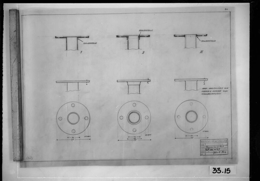
This image shows a technical drawing or a set of schematics. On the drawing, there are six different views of a cylindrical object with a flange. Two views show the object from the side with the flange being visible, labeled "Schnittstelle," likely referring to sectional views. The four other views present the object from two different angles, two from the top and two from the front, showing the circular face with bolt holes.
In the bottom right corner, there's an information box with various texts and numbers, typical for engineering or architectural plans. These often include the drawing number, project name, date, scale, and other relevant identifiers for the design in question. However, the actual text in the box is not clearly readable in this image.
The image appears to be a photograph of a physical drawing, as evidenced by the wear and tear on the paper's edges and the reflection on the glass that covers the drawing. There's a handwritten number "33.15" in the bottom right which may relate to either the photo inventory number or the drawing reference.
Anthropic Claude
Created by claude-3-haiku-20240307 on 2025-01-13
The image appears to be a technical drawing or diagram showing various design elements or components, likely for some kind of mechanical device or structure. The drawing includes several different views or configurations of what seem to be metal parts or supports, with detailed measurements and annotations provided. There are no human figures or faces visible in the image.
Created by claude-3-5-sonnet-20241022 on 2025-01-13
This appears to be a technical engineering drawing or blueprint showing mechanical components. The drawing shows three similar designs in both side view (top) and top view (bottom). Each design appears to be some kind of flange or mounting plate with a circular pattern and what looks like bolt holes around the perimeter. The side views show T-shaped cross-sections with annotations. The drawings include dimension lines and appear to be done in a professional drafting style typical of engineering documentation. The image is in black and white and appears to be a historical or archived document, given its appearance and framing.
Created by claude-3-opus-20240229 on 2025-01-13
The image shows a technical drawing or blueprint depicting what appear to be three different types of tables or pedestals labeled A, B, and C. The drawing provides dimensions and cross-sectional views of these circular structures. At the bottom, there is a note mentioning "Langemark Middel Gen. Transportmiddel", which may be referring to a transportation or logistics company. The drawing is labeled "33.15" in the bottom right corner, likely an identifying number for this particular blueprint or schematic.
Meta Llama
Created by us.meta.llama3-2-90b-instruct-v1:0 on 2025-01-13
This image is a technical drawing of a mechanical component, likely a part of a larger machine or device. The drawing is presented in black and white, with a white background and a black border around the edges.
Key Features:
- Component Design: The drawing depicts a circular component with a central hole and several smaller holes around its circumference. The component appears to be symmetrical, with identical features on both sides of the central axis.
- Dimensions and Measurements: The drawing includes various dimensions and measurements, which are likely used to specify the exact size and shape of the component. These measurements are written in a language that is not immediately recognizable, but they appear to be in a technical or engineering notation.
- Labels and Annotations: The drawing includes several labels and annotations, which provide additional information about the component and its features. These labels are written in the same language as the dimensions and measurements, and they appear to be descriptive of the component's function or purpose.
- Border and Frame: The drawing is surrounded by a black border, which helps to define the edges of the image and provide a clear visual boundary. The border is slightly worn and faded in some areas, suggesting that the drawing may have been handled or stored for an extended period.
Overall Impression:
The image presents a detailed and technical drawing of a mechanical component, complete with dimensions, measurements, and labels. The drawing appears to be a professional or industrial design, and it may have been used in the manufacture or assembly of a larger machine or device. The use of a black and white color scheme and a technical notation suggests that the drawing is intended for a specialized audience, such as engineers or technicians.
Created by us.meta.llama3-2-11b-instruct-v1:0 on 2025-01-13
The image is a black and white technical drawing, showcasing various parts of a machine or device. The drawing is presented on a sheet of paper, with a black border surrounding it.
Drawing Details:
- The drawing features several parts, each labeled with a number and a brief description in a foreign language.
- The parts include:
- A circular component with a central hole and a series of holes around its edge.
- A rectangular component with a flat top and a curved bottom.
- A cylindrical component with a rounded top and a flat bottom.
- A flat component with a series of holes and a curved edge.
Additional Elements:
- A small box in the bottom-right corner contains additional text and diagrams, likely providing further information about the parts or their assembly.
- A handwritten note in the bottom-right corner reads "33.15," which may indicate the drawing's number or a reference code.
Overall:
- The technical drawing appears to be a detailed illustration of various components that make up a larger machine or device.
- The use of labels and diagrams suggests that the drawing is intended for technical or engineering purposes, possibly for manufacturing or assembly instructions.
Amazon Nova
Created by amazon.nova-pro-v1:0 on 2025-01-13
The image is a black-and-white technical drawing on a piece of paper framed in a black border. The drawing appears to be a schematic or blueprint, likely for a mechanical or structural component. The paper has a grid-like background, which helps in accurately depicting the dimensions and alignment of the parts. The drawing includes several components, such as rectangular shapes, circular shapes, and lines connecting them. There are annotations and labels next to some of the components, possibly indicating measurements, part numbers, or descriptions. In the bottom right corner of the image, there is a label "33.15," which could be a reference number or a part identifier.
Created by amazon.nova-lite-v1:0 on 2025-01-13
The image appears to be a technical drawing or blueprint. It features a black-and-white illustration of a table or desk with a rectangular top and four legs. The drawing is labeled with various measurements and dimensions, indicating that it is a detailed technical drawing intended for manufacturing or construction purposes.
The table or desk is depicted from a top-down perspective, with the rectangular top and four legs clearly visible. The legs are evenly spaced and appear to be of equal length, suggesting a symmetrical design. The drawing includes various measurements and dimensions, such as the length, width, and height of the table, as well as the dimensions of the legs and other components.
The image also includes some text and labels, which are likely used to identify specific parts or features of the table. For example, there may be labels indicating the type of wood or material used for the table, the thickness of the legs, or the type of fasteners or hardware used to assemble the table.
Overall, the image appears to be a technical drawing of a table or desk, intended for use in manufacturing or construction. The detailed measurements and labels suggest that it is a precise and accurate representation of the table's design, intended to guide the production or assembly process.
Created by amazon.nova-pro-v1:0 on 2025-01-11
The image is a technical drawing on a white background, framed by a black border. The drawing is composed of various geometric shapes and lines, possibly representing a design or a component of a mechanical system. There are three rectangular sections at the top, each labeled with the text "JONSONVILLE" and a number, possibly indicating different versions or parts of the design. Below these, there are three circular components with holes in the center, each accompanied by a label and dimensions. The bottom section of the drawing includes a rectangular shape with a label and the number "33.15," which could be a reference number or a specific dimension. The drawing appears to be a technical blueprint or schematic, likely used for engineering or manufacturing purposes.
Created by amazon.nova-lite-v1:0 on 2025-01-11
The image appears to be a technical drawing or blueprint of some sort. It shows a series of diagrams and annotations related to a mechanical or engineering design. Here is a detailed description of the image:
The image is framed within a black border, suggesting it is a printed or scanned document.
The central portion of the image contains several diagrams and annotations. The diagrams appear to depict various components or parts of a mechanical system or device.
The diagrams are labeled with letters (I, II, III) and numbers, indicating different sections or views of the design.
Some of the diagrams show circular shapes with holes or cutouts, possibly representing flanges or mounting plates.
There are annotations and measurements written in a foreign language, likely French or German, indicating the origin or context of the design.
The bottom right corner of the image contains the number "33.15," which could be a reference number or identifier for this particular drawing.
The overall composition and style of the drawing suggest it is a technical blueprint or schematic used in engineering or manufacturing contexts.
In summary, the image appears to be a technical drawing or blueprint depicting various components and details of a mechanical or engineering design. The diagrams, annotations, and measurements suggest it is a technical document used for manufacturing, assembly, or maintenance purposes.
Google Gemini
Created by gemini-2.0-flash on 2025-05-17
Here is a description of the image:
The image is a black and white photograph of a framed technical drawing. The drawing appears to be a schematic diagram or blueprint for a mechanical component. The drawing features multiple views of the same object, including cross-sectional and top-down views, with dimensions indicated. There is German text on the drawing. The frame of the photograph is black. A wooden trim is visible to the left of the drawing. The bottom of the frame has the number "33.15" written on it.
Created by gemini-2.0-flash-lite on 2025-05-17
Here's a description of the image:
The image is a black and white architectural or engineering drawing framed in a black rectangular frame. The drawing appears to be a technical illustration, likely showing different views and details of a mechanical component.
Here's a breakdown of what I can discern:
- Content: The drawing features multiple views of a part, possibly a flange or a similar component with a circular base, a central hole, and bolt holes. There are top and side views, and some detail views are showing how the parts are assembled, including "Schweisstelle" (welding point) indicating these components are meant to be welded together. The bottom portion of the drawing has a table with some measurement information. The text on the table is in German.
- Layout: The drawing is neatly organized, with clear lines and annotations. The views are numbered, and dimensions are provided using lines with arrowheads and numerical values.
- Presentation: The original is likely a reproduction of a drawing or blueprint, as it appears to be a photograph of a drawing. The paper appears somewhat aged, and the whole picture has been preserved in a glass frame.
- Context: This image is likely an archival photo.
In essence, the image is a valuable snapshot of a technical drawing, providing insights into the design of a mechanical component.
Text analysis
Amazon


