Machine Generated Data
Tags
Color Analysis
Feature analysis
Amazon
| Monitor | 62.2% | |
Categories
Imagga
| interior objects | 94.6% | |
| text visuals | 5.1% | |
Captions
Microsoft
created on 2020-04-26
| a black and white photo of a clock | 49.7% | |
| a black and white photo | 49.6% | |
| a white and black clock | 44.8% | |
OpenAI GPT
Created by gpt-4 on 2025-03-09
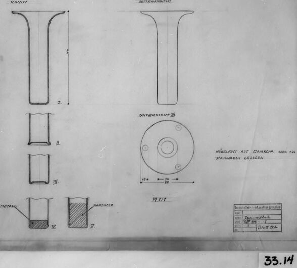
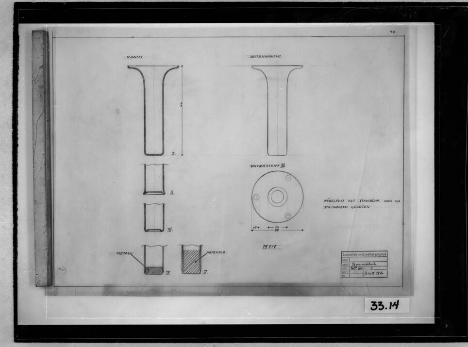
This image shows a technical drawing or blueprint of an object. The drawing appears to be neatly organized into different views of the component, with labels in German that could refer to various aspects or parts of the design. On the left part of the image, there are three separate diagrams (labeled I, II, III) showing different cross-sectional perspectives. The top one (I) shows an elongated section with a T-like end profile; the middle one (II) presents a shorter section with two opposing flattened sides; and the lowest one (III) displays two views, one showing a profile cut and the other a hatched area indicating material. On the right side of the image, there's a drawing of an object with a circular base, labeled "Unteransicht D" (which likely means "bottom view D" in German), and above it an "Ansichtenansicht" (which seems like a mislabeled term perhaps intended to be "Ansicht" for "view") that corresponds to a T-shaped profile similar to Diagram I on the left. Additionally, there is a label "Projekt aus Tahakin and Tahakins Gegern" on the right side corner, which might refer to the project's name or the materials used, although the context is unclear. The lower right corner contains a frame with indexing or reference information, such as "Projektnummer und Weltlaufnummer" (possibly project number and world sequence number), along with a date that could be associated with the project timeline. The image itself is monochromatic and has a black border, with markings that suggest age or reproduction, and it has the number "33.14" in the lower right corner, likely an archive or catalog reference number.
Created by gpt-4o-2024-05-13 on 2025-03-09
The image appears to be a technical drawing of a mechanical part. Here are the key components included in the drawing: 1. Various views of the object: - A side view labeled "Schnitt" (cut or section). - A front view labeled "Aussenansicht" (external view). - A bottom view labeled "Untersicht III" (bottom view III). 2. Detailed Sections: - Detailed sections labeled 'I', 'II', 'III', 'IV' and 'V' showing the part from different angles and cross-sections. 3. Annotations: - There are some German annotations indicating materials, such as "Stahlblech geschnitten" (cut steel plate) and "Metall" (metal). - The part consists of different materials and is detailed with dimensions in millimeters. 4. Scale Information: - A ruler is visible on the left side of the frame, and there are various dimensional measurements provided for the part in the form of numbers and units. 5. Title Block: - The drawing features a title block at the bottom right which contains information possibly about the part name, material specifications, date, drafter, and other details relevant to the production or examination of the part. Overall, the drawing is a precise technical depiction intended for engineering or manufacturing purposes, detailing the dimensions, views, and materials of a metal component.
Anthropic Claude
Created by claude-3-opus-20240229 on 2025-01-13
The image shows a technical drawing or blueprint of what appears to be some kind of metal fastener or connector. The drawing includes front, side and top views of the object with dimensions and annotations in German. There is a circular detail view as well showing threads or a textured surface. In the lower right is a small table with additional specifications. The drawing is framed and has an identification number "33.14" written below it.
Created by claude-3-haiku-20240307 on 2025-01-13
This image appears to be a technical drawing or blueprint depicting various geometric shapes and measurements. The drawing includes labeled sections labeled "Einheit" (German for "unit") and "Untermessung" (German for "sub-measurement"). There are several schematic diagrams and technical specifications shown. The image has a black border frame around it and a numerical label "33.14" in the bottom right corner, suggesting this may be part of a larger collection or archive of technical drawings.
Created by claude-3-5-sonnet-20241022 on 2025-01-13
This image appears to be a technical drawing or engineering schematic. It shows various views and cross-sections of what appears to be some kind of cylindrical or tubular component. The drawing includes: 1. Two side elevation views (labeled "SCHNITT" and "SEITENANSICHT") 2. Several cross-sectional views showing different internal details (labeled I, II, III, IV, and V) 3. A circular top view or plan view (labeled "UNTERANSICHT III") 4. Some dimensional markings and annotations in German The drawing is in black and white and appears to be a professional technical illustration, possibly from an engineering manual or manufacturing documentation. The component shown has a T-shaped profile when viewed from the side, with what appears to be some internal details or hollow sections shown in the cross-sectional views. The drawing has a number "33.14" visible in the corner and includes a title block typical of engineering drawings.
Meta Llama
Created by us.meta.llama3-2-90b-instruct-v1:0 on 2025-01-13
The image appears to be a technical drawing or blueprint, likely from the early 20th century. The drawing is rendered in black ink on white paper and features various components, including a T-shaped piece with measurements and labels in German. **Key Features:** * **T-Shaped Piece:** The central element of the drawing is a T-shaped piece with measurements and labels in German. This suggests that the drawing is related to engineering or manufacturing. * **Measurements and Labels:** The drawing includes measurements and labels in German, indicating that it was created for a specific purpose or project. * **Technical Details:** The drawing provides detailed technical information about the components, including dimensions, materials, and assembly instructions. * **Historical Context:** The style and content of the drawing suggest that it was created in the early 20th century, possibly during World War I or II. **Conclusion:** Based on the analysis, it is likely that the image is a technical drawing or blueprint from the early 20th century, related to engineering or manufacturing. The drawing provides detailed technical information about the components, including dimensions, materials, and assembly instructions. The historical context suggests that the drawing was created during a time of significant technological advancement and industrialization.
Created by us.meta.llama3-2-11b-instruct-v1:0 on 2025-01-13
The image is a black and white photograph of a technical drawing, likely from the early 20th century. The drawing appears to be a blueprint or schematic for a mechanical device or machine part, possibly related to engineering or manufacturing. Here are the key features of the image: * **Drawing Content:** + The drawing is divided into several sections, each with its own set of dimensions and labels. + There are various shapes and symbols used throughout the drawing, including lines, curves, and geometric shapes. + Some of the symbols appear to be abbreviations or codes, while others may represent specific materials or components. * **Drawing Style:** + The drawing is rendered in a traditional style, with hand-drawn lines and shading. + The paper appears to be of high quality, with a smooth texture and minimal creases or folds. + The drawing is framed by a thick black border, which adds to its formal and professional appearance. * **Background:** + The background of the image is a plain gray color, which helps to focus attention on the drawing. + There are no visible textures or patterns in the background, suggesting that it may be a scanned or digitized image. * **Overall Impression:** + The image conveys a sense of precision and attention to detail, which is consistent with the technical nature of the drawing. + The use of traditional drawing techniques and high-quality paper adds to the image's formal and professional appearance. + The overall impression is one of a carefully crafted and well-executed technical drawing, likely created for a specific purpose or application. In summary, the image presents a detailed and well-executed technical drawing, likely from the early 20th century. The drawing's content, style, and background all contribute to its formal and professional appearance, suggesting that it was created for a specific purpose or application.
Amazon Nova
Created by amazon.nova-pro-v1:0 on 2025-01-13
The image is a black-and-white technical drawing of a mechanical device, possibly a part of a larger machine or system. The drawing is framed within a black border, with a number "33.14" located at the bottom right corner. The drawing appears to be a blueprint, showcasing various components and their interconnections. The components are labeled with German text, indicating that the drawing is likely from a German-speaking region or a German company. The drawing includes a ruler on the left side, suggesting that it is a scaled representation of the actual object. The components are depicted in a detailed and precise manner, with lines and dimensions clearly marked. The drawing also includes a table with additional information, possibly related to the specifications or dimensions of the components. Overall, the image is a technical drawing of a mechanical device, likely used for engineering or manufacturing purposes.
Created by amazon.nova-lite-v1:0 on 2025-01-13
The image shows a technical drawing or blueprint of a mechanical component. The drawing is in black and white and appears to be an old photograph of the drawing. The drawing depicts a cylindrical component with a flanged end, likely a part of a mechanical assembly or machine. The drawing includes measurements and annotations in German, indicating the dimensions and specifications of the component. The drawing is labeled "33.14," suggesting it is part of a larger set of drawings or documentation. The image provides a detailed view of the component's design and construction, which would be useful for engineers, technicians, or manufacturers working with the component.
Text analysis
Amazon