Machine Generated Data
Tags
Color Analysis
Feature analysis
Amazon
Clarifai

Clarifai
| Picture frame | 97.5% | |
Categories
Imagga
created on 2020-04-26
| text visuals | 95.4% | |
| interior objects | 4% | |
Captions
Microsoft
created by unknown on 2020-04-26
| a black and white photo of a clock | 56.4% | |
| a black and white photo | 56.3% | |
| a white and black clock | 51.9% | |
Clarifai
No captions written
Salesforce
Created by general-english-image-caption-blip-2 on 2025-06-28
a black and white photograph of a drawing of a table
Created by general-english-image-caption-blip on 2025-05-03
a photograph of a drawing of a drawing of a door with a picture of a door
OpenAI GPT
Created by gpt-4 on 2025-03-06
The image shows a framed drawing or blueprint of a technical nature. There are three separate diagrams shown:
- On the top left, there's a side view of a structure labeled as "Ansicht" (which is German for "view" and commonly used in technical drawings to indicate a side view).
- In the center on the top, there's another view of what seems to be the same structure with the label "Schnitt" (which in German technical terms means "section" or "cut," indicating a sectional view of an object).
- On the top right, there is yet another view of the same structure marked "Ansicht," suggesting another angle or side view.
Below these diagrams is another drawing:
- A front view of a panel with four holes at the corners and a larger circle in the center, labeled "Th. 14/1."
There's text in German at the bottom of the image which seems to be detailing specifications or descriptions of the drawings, but the image resolution does not allow for the text to be read clearly.
Additionally, there's a label in the bottom right corner on a sticker, which appears to be an archive or library reference indicating the source or classification of the diagram, with the number "35.13."
The overall look of the document suggests it is an archival technical drawing, perhaps a historical document related to engineering or architecture.
Created by gpt-4o-2024-05-13 on 2025-03-06
The image depicts an architectural or engineering drawing. It features detailed, technical illustrations with annotations in German, likely for furniture or cabinetry. The drawing has multiple views of a component, including:
Elevation View (marked as "Aufriss" and "Seitenriss"):
- These views show the front (elevation) and side aspects of the component in two-dimensional form.
- Each view includes detailed lines and measurements, providing a visual representation of the component's structure and dimensions.
Sectional View (marked as "Schnittstelle"):
- This view cuts through the component to show its internal features at a certain point.
- It provides insight into the construction that isn't visible from the exterior views, highlighting aspects like the thickness of materials or the placement of internal parts.
Plan View (located on the bottom left corner):
- This top-down perspective shows the component's layout and arrangement as seen from above.
- Includes measurements and positions of key features such as screw holes and the overall dimensions of a mounting plate or base.
The drawing is presented on a single sheet with a label that includes additional details like project number, dimensions, date, and other specifications. The sheet is framed, indicating its importance or archival status. The bottom right corner includes a signature and date, signifying approval or validation of the drawing. The drawing provides comprehensive and precise information necessary for manufacturing or construction.
Anthropic Claude
Created by claude-3-haiku-20240307 on 2025-01-13
This image appears to be a technical drawing or blueprint. It contains several geometric shapes and diagrams, including vertical lines labeled "steutle" and "neustetle", as well as a circular shape with dimensions. There is also some text in German, but no clear indication of what the overall design or purpose of this drawing might be.
Created by claude-3-5-sonnet-20241022 on 2025-01-13
This appears to be a technical drawing or architectural sketch showing three different views of what looks like a structural support or mounting element. The drawing includes two elevation views (side views) showing vertical posts with horizontal elements at the top, and a plan view (top-down view) showing a square plate with four corner mounting points and a circular opening in the center. The drawing has some text labels and notations, though they're not entirely clear in this black and white image. There appears to be a reference number "38.13" in the bottom right corner. The drawing is presented in a formal technical style typical of engineering or architectural documentation.
Created by claude-3-opus-20240229 on 2025-01-13
The image shows a technical drawing or blueprint. It depicts the design and dimensions for some kind of mechanical part or assembly. The drawing includes front and side views with precise measurements annotated. There is a square cutout shown in the front view. The image is in black and white and appears to be an old photograph or scan of the original drawing, which is numbered "33.13" in the bottom right corner.
Created by us.anthropic.claude-3-5-sonnet-20241022-v2:0 on 2025-06-24
This appears to be a technical drawing or engineering diagram showing different views of what seems to be a mechanical component or part. The image is in black and white and appears to be an older technical document. It includes multiple views - what look like side elevations at the top and a plan view showing a square plate with a circular opening or hole in the center and four corner mounting points at the bottom. There's some text and notations on the drawing, including what appears to be a figure number "FIG. 314". The drawing is presented in a frame or border, and there's a number "38.13" visible in the corner of the frame.
Meta Llama
Created by us.meta.llama3-2-90b-instruct-v1:0 on 2025-01-13
The image depicts a technical drawing, likely from an architectural or engineering context, presented in black and white. The drawing is framed within a black border, with a white background that features a subtle texture resembling paper or cardboard. A small label at the bottom right corner displays the number "33.13" in black text.
The drawing itself consists of two main components: a detailed illustration of a rectangular structure on the left side, accompanied by a smaller inset diagram below it. On the right side, there is another detailed illustration of a similar rectangular structure, although it appears to be a variation or an alternative design. Both illustrations are rendered in fine black lines, with some annotations and labels written in a foreign language, possibly German or another European language.
In the bottom-right corner of the drawing, there is a small box containing illegible handwritten text, which may provide additional information about the project or the designer. Overall, the image suggests a meticulous and detailed approach to design, with careful attention paid to the proportions, dimensions, and features of the structures being depicted.
Created by us.meta.llama3-2-11b-instruct-v1:0 on 2025-01-13
The image presents a technical drawing, likely from the 20th century, showcasing a detailed design for a product or component. The drawing is rendered in black and white, with a focus on precision and clarity.
Key Features:
- Title and Labels: The top of the page features a title or label in German, although the exact text is illegible due to the image quality. Below this, two smaller labels are present, but their contents are also unclear.
- Drawing: The main drawing occupies most of the page, depicting a rectangular shape with a circular hole at its center. The rectangle is divided into two sections, each with a distinct design. The left section appears to be a flat surface, while the right section has a more complex structure, featuring a series of lines and shapes.
- Measurements and Annotations: Scattered throughout the drawing are various measurements and annotations, including numbers, letters, and symbols. These markings suggest that the drawing is intended for use in a technical or engineering context, where precise measurements are crucial.
- Border and Background: The drawing is set against a plain white background, which provides a clean and neutral backdrop for the technical details. A thick black border surrounds the drawing, adding a sense of depth and framing the image.
- Stamp and Number: In the bottom-right corner of the page, a small stamp or logo is visible, although its meaning is unclear. Adjacent to this is a handwritten number, "33.13," which may represent a unique identifier or reference code for the drawing.
Conclusion:
The image presents a detailed technical drawing that showcases a product or component design. The use of precise measurements and annotations suggests that the drawing is intended for use in a technical or engineering context. The image provides valuable insights into the design process and the attention to detail required in creating technical drawings.
Amazon Nova
Created by amazon.nova-pro-v1:0 on 2025-01-13
The image shows a drawing of a technical design with a black border. The drawing is on a piece of paper with some text written on it. There are two vertical structures with a label "Anion" on the left and "Schweifer" on the right. There is also a label "Schweifstelle" on the right side of the drawing. The drawing also includes a number "33.13" on the bottom right corner.
Created by amazon.nova-lite-v1:0 on 2025-01-13
This image appears to be a technical drawing or blueprint of a structure. It shows two vertical columns or posts with a horizontal beam connecting them at the top. The drawing is labeled with measurements and notes, indicating that it is a detailed plan for constructing this structure.
The columns are labeled "Anten" and "Schneller," suggesting that they may be part of a larger system or installation. The horizontal beam is labeled "Schwerstelle," which could refer to a specific type of support or load-bearing element.
The drawing also includes a label "11.111," which may be a reference number or identifier for this particular plan. Additionally, there is a note in the bottom right corner that reads "33.13," which could be another reference or measurement related to the structure.
Overall, this image appears to be a technical drawing for constructing a specific type of structure, possibly related to a larger installation or system. The detailed measurements and labels suggest that it is a precise and accurate plan for building this structure.
Created by amazon.nova-pro-v1:0 on 2025-01-12
The image is a technical drawing, likely an architectural or engineering blueprint, enclosed in a black frame. The drawing appears to be in black and white, with various components and annotations. In the upper left section, there is a vertical structure labeled "Aufzug," which is German for "elevator." Adjacent to it, on the right, is another vertical structure labeled "Schacht," meaning "shaft." Both structures are depicted with vertical lines and additional details.
Below these structures, there is a smaller, circular object with a central dot, possibly representing a mechanical component or a symbol for a specific function. The drawing also includes a reference number "14.114" and other annotations in German, such as "Hergestellt aus Stahlblech/Stangeneisen" (made from sheet steel/bar iron) and "Ziehpunkt" (drawing point), indicating the material and specific points of interest on the drawing.
In the bottom right corner, there is a reference number "33.13," which could be a page number or a section identifier within a larger document. The overall layout suggests that this is a detailed technical drawing intended for construction or engineering purposes, providing specific instructions and components for a particular project.
Created by amazon.nova-lite-v1:0 on 2025-01-12
The image appears to be a technical drawing or blueprint of a structural element, possibly a beam or column. The drawing is divided into two sections, labeled "Anbau" and "Schnitt," which likely refer to the front and cross-section views of the structure. The drawing shows the dimensions and details of the structural element, including the height, width, and thickness of the beams or columns. The text and numbers in the drawing are in German, indicating that it may be an original German document or a translation from German. The image also includes a reference number, "33.13," which could be used to identify the specific drawing or document. Overall, the image appears to be a technical drawing or blueprint used for engineering or construction purposes.
Google Gemini
Created by gemini-2.0-flash-lite on 2025-04-30
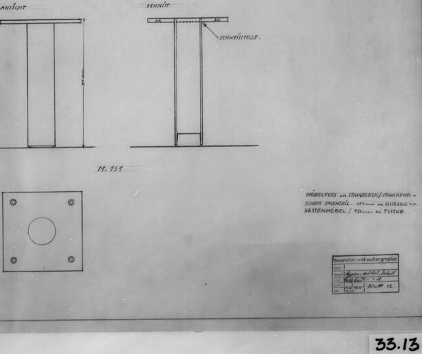
The image is a technical drawing of a piece of furniture, possibly a table or a pedestal. Here is a breakdown:
Overall Composition:
- The drawing is framed within a black border and the edges are faded with a few imperfections.
- It presents multiple views, including:
- An "Ansicht" (view/elevation)
- A "Schnitt" (section/cross-section)
- A plan view of the base
- There are annotations and labels in German.
Details:
- Views: The drawings show two basic rectangular legs, likely made of metal. The top seems to be a flat surface.
- "Schweissstelle": This label indicates a welding joint in the cross-section view.
- Base: The plan view shows a square base with a circular cutout in the center. There are also four smaller circles placed near each corner.
- Annotations: The German text seems to refer to the various components of the furniture. "Mobelfuss" means "furniture foot".
- Title Block: There is a title block in the bottom right. It lists the title, scale, and sheet number.
- Number: "33.13" is in the lower right, likely indicating the sheet number.
In Summary:
This is a professional architectural or design drawing for a piece of furniture. The various views give detailed information about the table or pedestal's construction and assembly.
Created by gemini-2.0-flash on 2025-04-30
Here is a description of the image:
The image shows a black and white architectural or engineering drawing of a piece of furniture, potentially a table. It is framed within a black border.
The drawing consists of three views of the object. At the top left, there's a simple elevation view, labeled "ANSICHT" (German for "view"). Next to it on the right is a sectional view, labeled "SCHNITT" (German for "cut"), indicating a cutaway view that exposes the interior construction. In this view, there's a note pointing to a "SCHWEISSTELLE" (German for "welding point").
Below these two views, there's a plan view of the base, showing a square with a circular hole in the center and smaller circles around the perimeter, indicating possible screw or bolt holes.
Underneath the drawings, there's a title or description block, possibly giving details about the material, component, or function of the furniture piece. The text includes terms like "MÖBELFUSS AUS STAHBLECH/TANKKEHR" (German for "furniture leg made of steel sheet/tank cover") and references to parts of a cabinet or table. The block also includes "Bauatelier prof. walter gropius" which may mean the studio or the professor who designed the piece.
At the bottom right corner, the number "33.13" is visible, perhaps indicating a drawing number or a catalog reference.
Mistral Pixtral
Created by us.mistral.pixtral-large-2502-v1:0 on 2025-06-03
The image shows a framed technical drawing, likely from an engineering or architectural context. Here is a detailed breakdown of the image:
Drawing Components:
- The drawing includes two main diagrams labeled "auflast" (load) and "zuglast" (tension load).
- The "auflast" diagram appears to show a vertical load applied to a structure.
- The "zuglast" diagram depicts a tension load applied to a structure, with an arrow indicating the direction of the tension force.
- Both diagrams seem to illustrate how loads are applied to a structural element, possibly a column or beam.
Additional Elements:
- There is a smaller diagram at the bottom left, showing a square with a circular hole in the center and four smaller circles at the corners, possibly representing bolt holes or fasteners.
- The drawing includes some text in German, which translates to "Load test of steel rods/steel cables" and mentions dimensions in millimeters.
- There is a handwritten note in the bottom right corner with a reference number "33.13."
Frame and Background:
- The drawing is framed in a black frame with a glass cover.
- To the left of the drawing, there is a vertical wooden object, possibly a ruler or a piece of wood used for scale or reference.
Labels and Annotations:
- The drawing is labeled with "Nr. 134" (Number 134) in the center.
- There is a stamp or label in the bottom right corner with some text and numbers, which might be related to the document's identification or classification.
Overall, the image appears to be a technical drawing used for engineering purposes, specifically related to the testing of steel rods or cables under different types of loads.
Qwen
No captions written
Text analysis
Amazon