Machine Generated Data
Tags
Color Analysis
Categories
Imagga
| interior objects | 76.7% | |
| text visuals | 22.4% | |
Captions
Microsoft
created by unknown on 2020-04-26
| a black and white photo of a microwave | 29.5% | |
Clarifai
created by general-english-image-caption-blip on 2025-05-21
| a photograph of a drawing of a drawing of a bathroom | -100% | |
OpenAI GPT
Created by gpt-4 on 2025-03-06
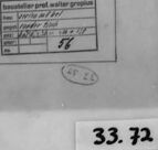
The image shows a black-and-white photograph of a technical drawing or blueprint. The drawing features a few different views of mechanical parts with dimensions and annotations indicating sizes and other specifications.
On the left side of the drawing, there is a top and front view of a circular piece with four holes. Above the circular object is another mechanical part shown from two different perspectives, one a front view and one side elevation, each with dimensions noted.
In the center of the drawing, there is a partial cross-section of a component, possibly a beam or some other structural element, marked with "PROJECTION" and indicating the shaping on one end of the part.
On the right side of the drawing, there is an outlined form with one corner cut away, again with dimensions, and below it appears to be either a detailed view or another component shown in dashed lines.
Toward the bottom center, there's text stating "STANDARD TITLE," likely indicating that this is a template or standard format for drawings.
In the lower right corner, there's a label or legend providing information about the drawing, such as the scale, draftsperson, checking engineer, approval, and date, among other data. However, the text in the label is too small to be legible in this image.
Surrounding the drawing is a frame or mat board, and the photograph shows some wear and aging, with artifacts such as smudges and discoloration on the edges of the photograph. In the bottom right corner of the image, there is a label with the text "33.72," which might refer to an inventory or identification number for the photograph or drawing.
The style of the drawing indicates it could be from the mid-20th century or earlier, a time when technical drawings were done by hand rather than with computer-aided design (CAD) software.
Created by gpt-4o-2024-05-13 on 2025-03-06
The image contains a technical drawing, likely of a component or an assembly. The drawing shows different views and projections typically used in engineering design:
- Front View: A frontal orthographic projection of the component, which includes dimensions and line annotations.
- Top View: A plan view showing a circular feature with four equally spaced holes around its perimeter.
- Side View: An orthographic side projection of the component, also including dimensions and annotation lines.
The sheet is bordered by a black outline, and the drawing itself is neatly placed within this boundary. Annotations likely contain additional details such as measurements, materials, or instructions for manufacturing. There is a box with filled details in the lower right corner, which probably contains metadata like the drawing title, scale, date, and draughtsman's information. The annotation "33.72" can be seen at the bottom right corner, which may correspond to a reference or catalog number for the drawing.
Anthropic Claude
Created by claude-3-5-sonnet-20241022 on 2025-01-14
This appears to be a technical drawing or engineering sketch showing various views of what might be a mechanical part or component. The drawing includes three different views or perspectives:
- A rectangular elevation view with measurements
- A circular plan view showing what appears to be bolt holes or mounting points
- A detail or section view showing some kind of joint or connection detail
The drawing is presented in a traditional technical drawing style with clean lines and appears to be done on paper with a border frame. There's what looks like a title block or information box in the bottom right corner, and the number "33.72" is visible at the bottom of the frame. The image is in black and white, likely a photograph or scan of an original engineering document.
Created by claude-3-opus-20240229 on 2025-01-14
The image shows a black and white technical drawing or blueprint. It appears to be an engineering diagram or schematic depicting the dimensions and layout of some mechanical component or device.
The drawing includes a side view showing the profile and measurements of the object. There are also some circular elements that could represent cross-sections or openings.
Various labels, numbers and lines provide additional details about the size, shape and structure of the depicted item. A signature or notation in the bottom right corner reads "33.72".
Overall, it has the look of a precise engineering drawing used to specify the design and manufacturing details for a part or assembly. The stark, high-contrast style is typical of technical blueprints and schematics.
Created by claude-3-haiku-20240307 on 2025-01-14
The image appears to be an architectural or engineering drawing, depicting various geometric shapes and measurements. The drawing includes a rectangle, a circle, and some other irregular shapes with corresponding dimensions and notes. The drawing seems to be part of a larger technical document or blueprint, as indicated by the catalogue number at the bottom right corner of the image.
Meta Llama
Created by us.meta.llama3-2-90b-instruct-v1:0 on 2025-01-14
This image depicts a technical drawing of a mechanical component, likely a part for an industrial machine or device. The drawing is presented on a white sheet of paper with a black border, featuring various measurements and annotations in black ink. The component appears to be a rectangular piece with rounded edges and a circular hole at its center.
The drawing includes several views of the component, including a top-down view, a side view, and a cross-sectional view. Each view provides detailed measurements and dimensions, allowing for precise fabrication or assembly of the part. The annotations include labels such as "33.72" in the bottom-right corner, which may refer to a part number or identification code.
Overall, this technical drawing serves as a blueprint for manufacturing or assembling the mechanical component, providing essential information for engineers, machinists, or other professionals involved in the production process.
Created by us.meta.llama3-2-11b-instruct-v1:0 on 2025-01-14
The image depicts a technical drawing or blueprint, featuring a black-and-white design with various geometric shapes and lines. The drawing is enclosed in a black frame, with a white background and a black border around it.
Key Features:
- Geometric Shapes: The drawing includes several geometric shapes, such as rectangles, circles, and triangles, which are likely used to represent different components or parts of a larger system.
- Lines: The drawing features various lines, including straight lines, curved lines, and dashed lines, which are used to connect the geometric shapes and provide additional information about the design.
- Labels: There are several labels on the drawing, including text and numbers, which provide additional context and information about the design.
- Border: The drawing is enclosed in a black frame, which provides a clear border around the design and helps to distinguish it from the surrounding background.
- Background: The background of the image is white, which provides a clean and neutral backdrop for the drawing.
Overall:
The image appears to be a technical drawing or blueprint, likely used in an engineering or architectural context. The drawing is well-organized and easy to read, with clear labels and annotations that provide additional information about the design.
Amazon Nova
Created by amazon.nova-pro-v1:0 on 2025-01-14
The image depicts a technical drawing of a mechanical component, possibly part of a larger assembly. The drawing is presented on a white background with a black border, which suggests it is a printed or scanned document. The drawing includes several geometric shapes, including rectangles, circles, and lines, which are used to represent different parts of the component. The drawing also includes text and numbers, which provide additional information about the component's dimensions, materials, and manufacturing processes. The overall appearance of the drawing suggests that it is a professional and detailed technical document, intended for use by engineers, designers, or manufacturers.
Created by amazon.nova-lite-v1:0 on 2025-01-14
The image appears to be a technical drawing or blueprint. It depicts a diagram with various lines, shapes, and labels. The drawing is enclosed within a black border, giving it a professional and organized look. The diagram consists of several components, including a rectangular shape with a label "33.72" at the bottom right corner. The rectangular shape is divided into smaller sections, and there are lines connecting different parts of the diagram. The labels and measurements provide specific details about the components and their relationships. Overall, the image represents a technical illustration or schematic, likely used in engineering, architecture, or a related field.
Created by amazon.nova-pro-v1:0 on 2025-01-12
The image features a black-and-white architectural or engineering drawing on a piece of paper. The drawing is placed inside a transparent plastic sheet, which is then enclosed within a black frame. The drawing consists of various shapes and lines, including rectangles, circles, and lines with measurements and annotations. The drawing appears to be a detailed plan or blueprint for a specific structure or component.
Created by amazon.nova-lite-v1:0 on 2025-01-12
The image is a black and white technical drawing, likely from an architectural or engineering context. It shows a detailed plan view of a structure, possibly a section of a building or a mechanical component. The drawing is encased in a frame with a black border, enhancing its presentation.
The drawing itself contains various elements. In the upper section, there is a rectangular shape with measurements and annotations, indicating dimensions and possibly material specifications. Below this, there is a circular element with a central hole, possibly representing a pipe or a similar cylindrical component. This part of the drawing is labeled with the number "33.72," which could be a reference to a specific part number or a measurement.
The lower part of the drawing includes a table or grid with several rows and columns, likely detailing specifications or data related to the components shown above. The text in this section is partially obscured, but it appears to include technical terms and possibly numerical values.
The overall layout of the drawing is organized and precise, indicating a professional and detailed approach to the design or analysis of the structure or component. The use of a frame suggests that this drawing is intended for presentation or documentation purposes, possibly for review or approval by stakeholders.
Google Gemini
Created by gemini-2.0-flash on 2025-05-17
Here's a description of the image:
The image shows a framed technical drawing, presented in black and white. The drawing features several geometric figures and text annotations, all arranged within a rectangular frame. The geometric shapes include lines, circles, and rectangles, which likely represent various aspects of a technical design.
The drawing is mounted on a transparent sheet, possibly glass or plastic, within a thicker, dark-colored frame. Two rectangular objects, possibly rulers or guides, are positioned on opposite sides of the drawing, seemingly holding it in place. A numerical code, "33.72," is visible in the lower right corner, likely serving as a catalog or identification number.
Overall, the image appears to be a photograph of a technical drawing, capturing its details and presentation style.
Created by gemini-2.0-flash-lite on 2025-05-17
Here's a description of the image:
The image depicts a technical drawing, likely an architectural or engineering blueprint. It is framed in a dark, rectangular border with vertical strips running along the sides. The drawing itself appears to be on a translucent sheet of paper or film.
The drawing presents several views of an object. There are:
- Multiple Views: It has at least three different representations of a structure, including a side view, a top view, and another view showing a partial cut-away.
- Geometric Shapes: The drawing makes use of circles, squares, and straight lines, indicating a mechanical or structural design.
- Annotations: There is text and possibly dimensions written on the drawing.
- Reference and Scale: Some textual annotations and labels provide more context and information about the design.
The number "33. 72" is located in the bottom right corner of the framed image.
Mistral Pixtral
Created by us.mistral.pixtral-large-2502-v1:0 on 2025-05-27
The image depicts a framed technical drawing or blueprint. The drawing appears to be a mechanical or architectural design, possibly for a component or part of a larger structure. Key features include:
Main Drawing: The central part of the drawing shows a detailed plan view of a mechanical component. It includes various lines, curves, and dimensions, indicating precise measurements and specifications.
Inset Drawings: There are smaller inset drawings within the main drawing. One inset shows a circular component with labeled dimensions, likely representing a cross-section or detailed view of a specific part. Another inset shows a rectangular shape with dimensions, possibly a different view or another component.
Annotations: The drawing includes annotations and labels, such as "PLAN VIEW" and "SECTION A-A," which help in understanding the different views and sections of the component.
Scale and Measurements: The drawing includes scale indicators and measurements, which are essential for accurate manufacturing or construction.
Frame and Labels: The drawing is framed, and there are labels on the frame, including "33.72" at the bottom right corner, which might be an identification or catalog number.
Tools: There are two rulers or straightedges placed on either side of the frame, possibly used for measuring or drawing straight lines.
Overall, the image captures a detailed and precise technical drawing, likely used in engineering or architecture for the design and construction of a specific component.
Text analysis
Amazon