Machine Generated Data
Tags
Color Analysis
Feature analysis
Amazon
| Monitor | 67% | |
Categories
Imagga
| text visuals | 98.9% | |
Captions
Microsoft
created by unknown on 2020-04-26
| a clock hanging on the wall | 45.9% | |
| a clock hanging on a wall | 44% | |
| a clock on a table | 43.8% | |
Clarifai
created by general-english-image-caption-blip on 2025-05-19
| a photograph of a drawing of a plan for a house | -100% | |
OpenAI GPT
Created by gpt-4 on 2025-03-05
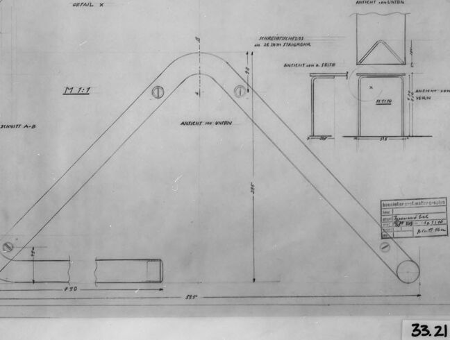
This is an image of a technical drawing or engineering blueprint. The drawing is quite detailed and appears to show the design of a mechanical part or structure. Visible details include various annotations, dimensions, and labels providing information about the components and their specifications. The drawing includes a side view of an arched structure with precise measurements, as well as an inset detailed view of an individual part with additional dimensions.
A textbox provides further information that seems to refer to the material or the procedure of the design, though the specific text is too small to read clearly in this image. The entire drawing is framed, possibly indicating it is a scanned or photographed copy. Identifying marks such as "33.2I" are present, potentially for archival, cataloging, or reference purposes.
Created by gpt-4o-2024-05-13 on 2025-03-05
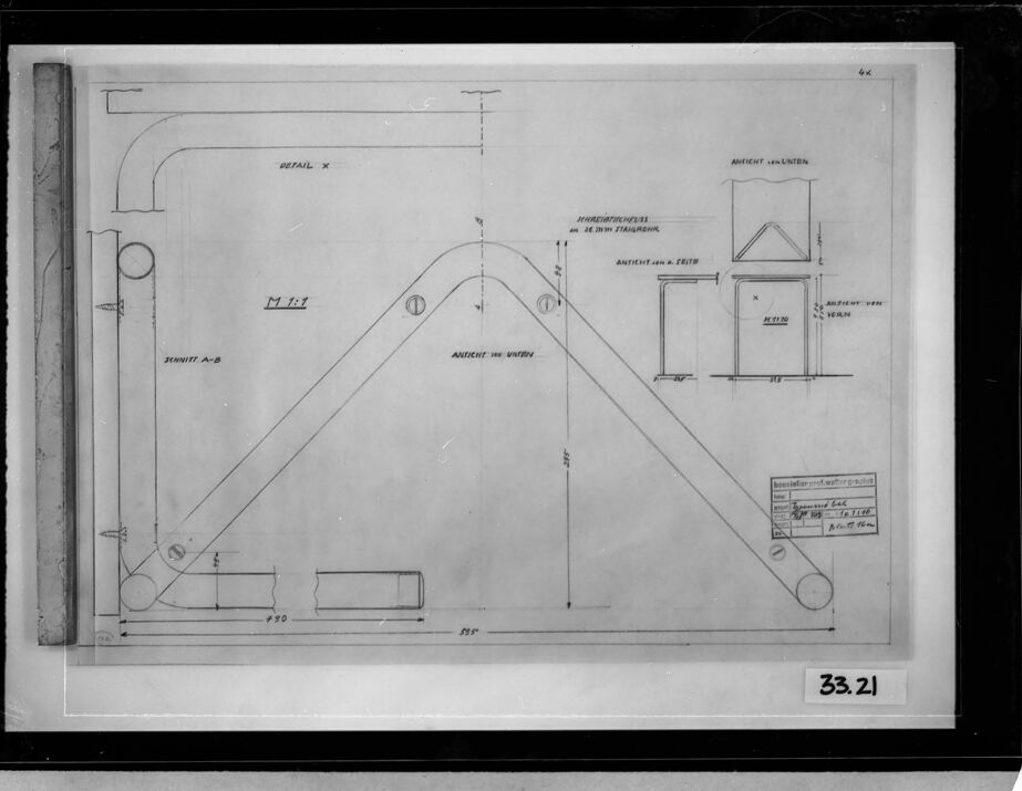
The image is a technical drawing or blueprint, enclosed in a frame. It contains detailed geometric and engineering details for a specific mechanical part. This specific blueprint appears to depict a mechanical arm or bracket, with measurements and specifications including various angles and lengths.
Key features:
- The drawing is primarily made up of straight lines, angles, and curved corners.
- Various sections are labeled with letters and symbols, indicating different views or components such as "Detail X" and "Schnitt A-B."
- Precise dimensions are indicated, including 950mm and 828mm on the main part of the arm or bracket.
- There are annotations in German, suggesting that this drawing originates from a German-speaking context.
- A smaller box in the lower right corner of the drawing includes additional technical details and what appears to be a title and possibly a date or project number.
- The drawing includes multiple views of the part, such as side, front, and sectional views to give a comprehensive understanding of its structure.
- The identification number "33.21" is visible on a label at the bottom right of the frame.
Overall, the blueprint provides a highly detailed and technical representation of the mechanical part, suitable for manufacturing or engineering analysis.
Anthropic Claude
Created by claude-3-opus-20240229 on 2025-01-13
The image shows a technical drawing or blueprint of what appears to be a triangular architectural structure or building element. The drawing includes various measurements, angles, and labels indicating the dimensions and specifications of the structure. It has a symmetrical shape with angled sides that meet at a peak in the center. The image is in black and white and has a vintage or aged appearance, suggesting it may be an older architectural plan or design document.
Created by claude-3-haiku-20240307 on 2025-01-13
The image appears to be an engineering or architectural drawing. It contains various technical diagrams, measurements, and annotations. The central focus of the drawing seems to be a triangular or funnel-shaped structure with additional details and measurements surrounding it. There are also smaller illustrations or schematics on the right side of the drawing. The overall image suggests it is a detailed technical plan or schematic, likely related to an engineering or construction project.
Created by claude-3-5-sonnet-20241022 on 2025-01-13
This appears to be a technical engineering or architectural drawing/blueprint showing detailed schematics of some kind of triangular or A-frame structure. The drawing includes multiple views and cross-sections, with various measurements and annotations in what appears to be German text. There are several detail views shown in the upper right corner of the drawing that appear to show different joint or connection details. The main view shows a triangular frame with rounded corners at the base. The drawing is labeled with dimensions and includes what looks like a scale or title block in the lower right corner. The image is in black and white and appears to be an older or historical technical document, possibly photographed or archived.
Meta Llama
Created by us.meta.llama3-2-90b-instruct-v1:0 on 2025-01-13
The image presents a technical drawing of a machine part, likely a component for a larger device or system. The drawing is rendered in black and white, with various lines, shapes, and annotations that provide detailed information about the part's design and specifications.
Key Features:
- Central Component: The central element of the drawing appears to be a curved metal piece, possibly a bracket or a support structure. It features a distinctive arc shape, with two circular ends and a flat base.
- Dimensions and Measurements: The drawing includes several measurements and dimensions, which are likely used to specify the exact size and shape of the part. These measurements are represented by numbers and symbols, such as "33.21" and "6x," which may indicate the part's length, width, or other critical dimensions.
- Annotations and Labels: The drawing contains various annotations and labels that provide additional context and information about the part. These include text notes, arrows, and symbols that highlight specific features or components of the design.
- Background and Context: The background of the image is a plain gray color, which helps to focus attention on the technical drawing. The overall context of the image suggests that it is a professional or industrial setting, where engineers or designers are working on a project that requires precise technical specifications.
Conclusion:
In summary, the image presents a detailed technical drawing of a machine part, complete with measurements, annotations, and labels. The drawing provides a clear and accurate representation of the part's design and specifications, making it an essential tool for engineers, designers, and manufacturers who need to create or assemble the component.
Created by us.meta.llama3-2-11b-instruct-v1:0 on 2025-01-13
The image presents a technical drawing of an unknown object, likely a piece of furniture or machinery, with various measurements and labels in German. The drawing is rendered in black ink on white paper, surrounded by a black border.
- Drawing
- The drawing depicts a complex shape with multiple lines, curves, and angles.
- It features several measurements and labels in German, including "AMTICHT UND UNTEREIN" and "33.21".
- The drawing appears to be hand-drawn, with some imperfections and smudges visible.
- Background
- The background of the image is a light gray color, which provides a subtle contrast to the black border and white paper.
- There are no other objects or features visible in the background.
- Border
- The black border surrounding the drawing is thick and prominent, drawing attention to the technical drawing itself.
- The border is slightly worn and faded in some areas, suggesting that the image may have been handled or stored for an extended period.
In summary, the image presents a detailed technical drawing of an unknown object, complete with measurements and labels in German. The drawing is surrounded by a black border, which adds to its overall aesthetic appeal. While the image does not provide any additional context or information about the object being drawn, it is clear that the drawing is a carefully crafted representation of a complex shape or design.
Amazon Nova
Created by amazon.nova-pro-v1:0 on 2025-01-13
The image is a black-and-white architectural drawing, framed in a black border, with a number "33.21" at the bottom right corner. The drawing depicts a detailed plan of a structure, possibly a building or a part of a building, with various annotations and measurements. The plan includes rectangular and square shapes, lines, and labels, indicating different elements and dimensions of the structure. The drawing is precise and technical, likely used for construction or architectural purposes.
Created by amazon.nova-lite-v1:0 on 2025-01-13
The image is a technical drawing or blueprint, likely from an architectural or engineering context. The drawing is contained within a black-bordered frame, indicating it is a printed or scanned document. The drawing itself is a schematic representation of a structure or component, possibly related to construction or mechanical design.
The drawing includes various annotations and measurements, indicating it is a detailed plan. The annotations are written in a foreign language, possibly German or another European language. The drawing features several labeled sections, including "M 1:7," "Zehnit A/B," and "Ansicht von," suggesting it is a plan view or elevation of a structure.
The drawing also includes a table or legend with measurements and specifications, such as "4k," "33.21," and "100," which likely correspond to dimensions or quantities related to the structure or component being depicted.
Overall, the image appears to be a technical drawing or blueprint for a structure or component, with detailed annotations and measurements in a foreign language. The drawing is contained within a black-bordered frame, indicating it is a printed or scanned document.
Created by amazon.nova-lite-v1:0 on 2025-01-11
The image is a technical drawing or blueprint, likely from an architectural or engineering context. The drawing is framed by a black border, which adds a professional and clean look to the image. The drawing itself is predominantly white, with various lines, shapes, and annotations in black. The drawing appears to be a detailed plan or section of a structure, possibly a building or a part of a mechanical system.
At the top of the drawing, there is a label that reads "DETAIL X," indicating that this is a detailed section or view of a specific part of the overall design. The drawing includes various annotations and labels, such as "M 1:1," "ZEHNIT A/B," and "ANTENT," which likely refer to specific measurements, components, or technical terms related to the design.
The drawing also includes a table or legend with measurements and labels, providing additional information about the design elements. The overall composition of the image is well-organized and easy to read, with clear lines and annotations that allow for a detailed understanding of the design.
Overall, the image appears to be a professional and technical drawing, likely used for planning, construction, or engineering purposes. The detailed annotations and labels suggest that it is a highly specific and precise representation of a particular design element or component.
Created by amazon.nova-pro-v1:0 on 2025-01-11
The image depicts a technical drawing, likely an architectural or engineering blueprint. It features various lines, dimensions, and annotations that suggest a detailed plan for a structure or system. The drawing includes a rectangular frame with a grid-like structure inside, which appears to be a section of a larger design. The grid is divided into smaller sections, possibly indicating different components or areas of the design. There are also various symbols and labels, such as "M1-1" and "M1-2," which could represent specific parts or measurements. The overall appearance suggests a precise and organized layout, typical of technical drawings used in construction or engineering projects.
Google Gemini
Created by gemini-2.0-flash on 2025-04-29
Here is a description of the image:
The image displays a technical drawing encased in a black frame, with a white border highlighting the drawing itself. The drawing appears to be a schematic, detailing various angles and sections of an unknown structure or object.
At the top left, "DETAIL X" is labeled, with an accompanying sketch showing a curved section. Below this is "SCHNITT A-B", which translates to "Section A-B", and features what looks like a vertical cross-section of a component.
The center of the drawing presents a large triangular structure labeled "M 1:1", indicating a 1:1 scale. There are multiple labels in German, such as "ANTICHT UNTEN" (View from below), and some technical notes like "STAHLRONN".
Additional smaller schematics can be seen on the right side, each labeled "ANTICHT" followed by a direction. A box containing some handwritten notes or specifications is visible at the lower right.
The number "33.21" is prominently displayed in the bottom right corner of the frame.
Created by gemini-2.0-flash-lite on 2025-04-29
Here's a description of the image:
Overall:
The image presents a technical drawing, likely an architectural or engineering blueprint. It's a detailed, hand-drawn plan encased in a black frame.
Drawing Elements:
- Geometric Shapes: The drawing primarily features lines, circles, and rectangles, forming a complex, angular structure. There is a large triangular shape dominating the center.
- Details: Sections like "DETAIL X", "SCHNITT A-B" (Section A-B) and "ANTICHT" (View) are labeled.
- Dimensions: The drawing includes numerical dimensions, indicating measurements (e.g., 430, 595).
- Scale: It is marked with "M 1:1", meaning the drawing is at a 1:1 scale, i.e., the drawing is the same size as the object it represents.
- Small Drawings: Within the main plan, there are smaller, isolated drawings providing different perspectives or details.
- Text: The image contains handwritten text in German. The text "ANTICHIT" and "STAHLROHR" can be made out.
Additional Details:
- The drawing appears to be made on a translucent material, possibly tracing paper or vellum, and attached to a backing board.
- There are indications of a drafting tool such as a ruler or t-square.
- The number "33.21" is printed at the bottom right corner of the drawing.
Inferred Purpose:
Based on the geometric shapes, dimensions, and annotations, the drawing likely represents a mechanical component, possibly part of a larger structure. The different views suggest a need to show its construction and how it fits within a larger system.
Mistral Pixtral
Created by us.mistral.pixtral-large-2502-v1:0 on 2025-05-25
The image is a technical drawing or blueprint, likely for a mechanical or structural component. Here's a detailed summary:
Main Structure:
- The central part of the drawing depicts a triangular structure with two main arms converging at the top.
- There are various annotations and dimensions provided around this structure, indicating specific measurements and details.
Components and Details:
- On the left side, there is a detailed view labeled "Detail X," showing a close-up of a specific part, possibly a joint or connection.
- The left side also includes a section labeled "Section A-B," providing a cross-sectional view of a part of the structure.
- There are several smaller inset drawings and sections labeled "Detail Y" and "Detail Z," which provide additional views or details of specific components.
Annotations:
- The drawing includes various annotations in what appears to be Russian, indicating different parts and dimensions.
- Terms like "Anker" (anchor) and "Hardware" are mentioned, suggesting the presence of anchoring points and hardware components.
- There are also notes and calculations in a box at the bottom right, providing additional technical information.
Dimensions and Measurements:
- The drawing includes numerous dimension lines and measurements, indicating the precise sizes and positions of various parts.
- These measurements are crucial for the accurate construction or assembly of the component.
Presentation:
- The drawing is framed and appears to be displayed, possibly in a museum or exhibition setting.
- The number "33.21" is visible at the bottom right, which could be an inventory or catalog number.
Overall, the image is a detailed technical drawing of a mechanical or structural component, complete with dimensions, annotations, and various detailed views of specific parts.
Text analysis
Amazon