Machine Generated Data
Tags
Color Analysis
Feature analysis
Amazon
Clarifai
AWS Rekognition
| Monitor | 65.1% | |


Categories
Imagga
created on 2020-04-27
| text visuals | 58% | |
| paintings art | 29.4% | |
| interior objects | 7% | |
| food drinks | 3.8% | |
| cars vehicles | 1.2% | |
Captions
Microsoft
created by unknown on 2020-04-27
| an old photo of a clock | 51.6% | |
| a black and white photo of a clock | 43.4% | |
| a screen shot of a clock | 43.3% | |
Clarifai
No captions written
Salesforce
Created by general-english-image-caption-blip on 2025-05-18
a photograph of a drawing of a drawing of a house
Created by general-english-image-caption-blip-2 on 2025-06-28
a black and white photograph of a building with drawings
OpenAI GPT
Created by gpt-4 on 2025-03-08
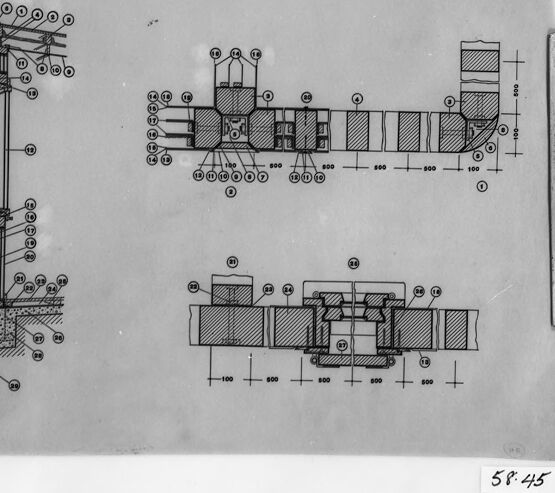
The image shows a black and white technical drawing or schematic of what appears to be a part of a machine, structure, or system. The drawing includes various elevational views and cross-sectional details, with numerical labels likely indicating dimensions or reference points.
To the left side of the image, there's a perspective view showing a component with multiple circular points, possibly connection points, bolts, or rivets. The central part of the drawing has a plan view or a top-down view with the same circular points and some striped patterns that could represent different materials or components.
The bottom of the image contains what looks like a sectional view, presented in a way to show the internal structure or layering of the components.
There are numbers indicating measurements in a scale, suggesting that the drawings are precise and meant to guide the fabrication or construction process. The annotation '51:45' appears in the bottom right corner, possibly a reference or identification number for the drawing within a set. The drawing is framed by a black border, and there's a white margin around it with three visible edges.
Moreover, it's apparent that the image has been photographed or scanned from a physical copy, as indicated by the presence of a glass or transparent cover over the drawing, visible at the right edge where it captures a reflection.
Created by gpt-4o-2024-05-13 on 2025-03-08
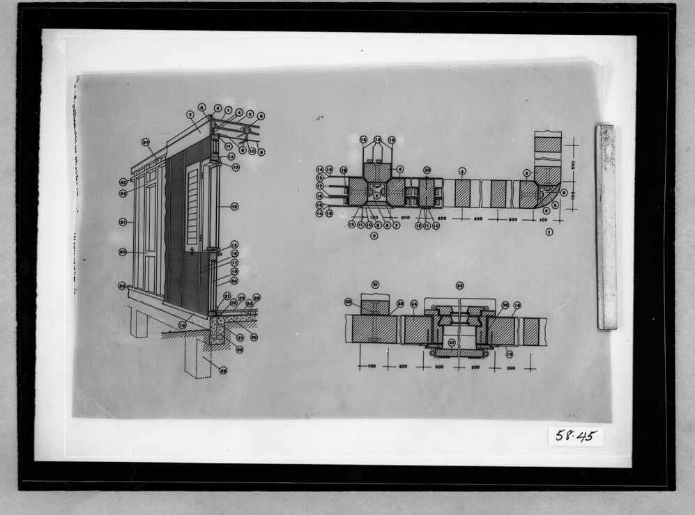
This image is a technical architectural drawing, likely of a window or wall section with detailed construction components. It contains three sections:
On the left side, there is a vertical cross-sectional diagram of what appears to be a window and wall assembly. This section includes detailed annotations indicating various parts and materials used in the construction, such as windows, shutters, structural framing, and foundation.
The middle section shows a horizontal cross-sectional view possibly representing the wall structure from an overhead perspective. It includes measurements, symbol annotations, and detailed parts of the construction assembly.
The bottom right section provides a detailed cross-section which seems to highlight a specific construction detail, perhaps focusing on the intersection or connection of different structural elements. It also includes measurements and annotations for clarity.
The entire drawing is framed within a black rectangular border and appears to be a draft or study, as suggested by the hand-written number "58.45" in the lower right corner.
Anthropic Claude
Created by claude-3-opus-20240229 on 2025-01-14
The image shows a technical drawing or blueprint of what appears to be an electrical transformer or power supply unit. The drawing contains front and side views of the device with various components and parts labeled with numbers and connected by lines. Dimensions are provided indicating the size and spacing of different elements. The drawing is done with thin black lines on a light gray background and is labeled "SP-45" in the bottom right corner, likely an identifier or part number for this schematic.
Created by claude-3-haiku-20240307 on 2025-01-14
The image appears to be a technical drawing or schematic diagram of an architectural or engineering component. It contains detailed sectional views and labeled components, suggesting it is an engineering or design document. The drawing appears to be in black and white, with various geometric shapes, lines, and numerical dimensions annotating the different parts of the structure or system being depicted. Without being able to identify any specific individuals, the image seems to provide technical details and specifications for some kind of structural or mechanical system.
Created by claude-3-5-sonnet-20241022 on 2025-01-14
This appears to be an architectural or engineering technical drawing showing detailed construction plans. The image includes both a perspective view and cross-sectional diagrams. On the left side, there's a detailed drawing of what appears to be a door or window frame assembly, showing various components numbered for reference. On the right side, there are two horizontal cross-sectional views with measurements and part numbers indicated. The drawings appear to be professionally drafted and include dimension markings in what might be millimeters or similar units. The drawing is presented in black and white and appears to be a historical document, possibly from an architectural archive, as suggested by the frame and photograph quality.
Created by us.anthropic.claude-3-5-sonnet-20241022-v2:0 on 2025-06-24
This image appears to be a technical architectural or engineering drawing showing detailed construction plans. On the left side, there's a cross-sectional view of what looks like a door or window frame assembly, showing various components and their connections. On the right side, there are two horizontal sectional views with measurements and numbered annotations. The drawing is in black and white, appears to be professionally drafted, and includes dimension lines and reference numbers throughout. It's presented in what appears to be a black frame or border, and there's a number "58-45" visible at the bottom right corner. The style suggests this is likely a vintage or historical technical drawing, possibly from architectural or construction documentation.
Meta Llama
Created by us.meta.llama3-2-90b-instruct-v1:0 on 2025-01-14
This image is a technical drawing of a building or structure, likely a house or cabin. The drawing is presented in black and white, with various sections and details labeled with numbers and letters. The drawing appears to be a blueprint or architectural plan, showcasing the design and layout of the building.
The drawing is divided into several sections, each highlighting different aspects of the structure. Some sections appear to show the exterior of the building, while others depict interior features such as windows, doors, and rooms. The use of numbers and letters suggests that the drawing is intended for construction or renovation purposes, providing detailed instructions for builders or contractors.
Overall, the image presents a detailed and technical representation of a building's design and layout, likely intended for professional use in the construction or architecture industry.
Created by us.meta.llama3-2-11b-instruct-v1:0 on 2025-01-14
The image presents a technical drawing of a building, showcasing its design and layout. The drawing is rendered in black and white, with a focus on the building's exterior and interior features.
Key Features:
- Building Design: The building appears to be a single-story structure with a rectangular shape, featuring a flat roof and a simple facade.
- Windows and Doors: The drawing highlights the placement of windows and doors, providing insight into the building's functionality and purpose.
- Dimensions: The drawing includes measurements and dimensions, allowing for a precise understanding of the building's size and proportions.
- Labels and Annotations: Various labels and annotations are scattered throughout the drawing, likely indicating specific components or features of the building.
- Background: The background of the drawing is a light gray color, providing a clean and neutral contrast to the black lines and text.
Overall Impression:
The technical drawing provides a detailed and informative representation of the building's design and layout. The use of black and white lines and text creates a clear and concise visual representation, making it easy to understand the building's features and dimensions. The inclusion of labels and annotations adds an extra layer of detail, allowing for a more comprehensive understanding of the building's design and functionality.
Amazon Nova
Created by amazon.nova-pro-v1:0 on 2025-01-14
The image is a black-and-white photograph of a technical drawing. The drawing is framed within a black border and appears to be a detailed blueprint or schematic. The drawing consists of multiple sections, each labeled with numbers and letters, indicating different parts or components of a structure or machine. The drawing is placed on a piece of paper, which is also framed within the black border. The paper appears to be old and worn, with some creases and tears visible. The drawing is accompanied by a ruler, which is placed on the right side of the paper. The ruler is used to measure the dimensions of the drawing and ensure accuracy. Overall, the image conveys a sense of precision and attention to detail, typical of technical drawings used in engineering or construction.
Created by amazon.nova-lite-v1:0 on 2025-01-14
The image appears to be a technical drawing or blueprint of a structure or device. It shows a black-and-white illustration of a rectangular-shaped object with various components and measurements labeled. The drawing is enclosed within a black frame, and there is a number "58.45" written in the bottom right corner.
The object in the drawing seems to be a type of mechanical or engineering structure, possibly related to a pump or valve system. It consists of several interconnected parts, including cylindrical sections, rectangular blocks, and smaller components. The drawing includes measurements and labels for various dimensions and features of the structure.
The purpose of this drawing is likely to provide detailed instructions or specifications for constructing or assembling the depicted object. It serves as a visual guide for engineers, technicians, or manufacturers to build the structure accurately according to the provided dimensions and design.
Overall, the image represents a technical illustration or blueprint of a mechanical or engineering component, with measurements and labels to guide its construction or assembly.
Created by amazon.nova-lite-v1:0 on 2025-01-11
The image is a black-and-white technical drawing or blueprint, possibly related to architectural or engineering design. The drawing is framed within a black border and appears to be a technical illustration with various components and annotations. The drawing is divided into sections, with the left side featuring a detailed view of a structure, possibly a building or a mechanical component, with labeled parts and dimensions. The right side of the drawing contains a more abstract representation, possibly a cross-section or a schematic diagram, with labeled elements and measurements. The drawing includes a scale bar on the right side, indicating the scale of the illustration. The image has a watermark or reference number "58.45" in the bottom right corner, suggesting it may be a specific drawing or document within a larger set or collection.
Created by amazon.nova-pro-v1:0 on 2025-01-11
The image features a black-and-white photograph of a framed document that is likely a technical drawing or blueprint. The document is placed in a black frame with a white border, which is placed on a gray background. The document itself contains three different technical drawings of a machine or structure, each with a detailed layout and measurements. The drawings are labeled with numbers and letters, and there are also some annotations and notes written in the margins.
Google Gemini
Created by gemini-2.0-flash-lite on 2025-05-17
Here's a description of the image:
The image presents an architectural blueprint or technical drawing framed within a black border. The drawing is monochromatic, likely a black and white scan. It features several views of a structure:
- Left View: A detailed elevation view of the front-left corner of the structure. It illustrates the facade of a building with a door, window, and exterior cladding. Various components are labeled with numbered callouts. The base is shown supported by concrete piers.
- Top View: A plan view of the building layout, likely a cross-section or top-down view. Dimensions are provided along the horizontal lines.
- Bottom View: Another plan view, possibly a cross-section, with dimensions along the horizontal axis.
The drawing style is technical, with solid lines representing the structure and hatched areas denoting materials or internal components. The overall effect suggests a professional architectural rendering for construction or design purposes. The lower right-hand corner of the image shows the numbers "58.45", likely a catalog or reference number.
Created by gemini-2.0-flash on 2025-05-17
Here is a description of the image:
The image is a black and white photograph of an architectural drawing mounted inside a black frame with a white border. The drawing is of a building section, showing construction details.
The drawing is composed of three distinct sections: a front elevation, a horizontal floor plan, and a sectional floor plan. Each section has numerous callouts with numbered circles and leader lines, indicating specific materials and construction elements.
The front elevation shows the vertical view of the building, highlighting the windows, siding, roof overhang, and foundation. The horizontal floor plan is a top-down view, illustrating the layout of walls and partitions. The sectional floor plan cuts through the building horizontally to show the internal construction layers.
The drawing is detailed with dimensions written beside the lines. The photograph is mounted on a black frame, surrounded by white paper. The number "58.45" is handwritten in the bottom right corner of the drawing. A rectangular grey and white object, possibly a ruler or scale, is placed along the right edge of the drawing.
Mistral Pixtral
Created by us.mistral.pixtral-large-2502-v1:0 on 2025-06-03
The image shows a technical drawing or blueprint, likely of a mechanical or industrial component. The drawing is detailed and includes multiple views of the object:
Main View (Left Side):
- This is an isometric or perspective view showing the overall structure of the component.
- The drawing includes various parts labeled with numbers, indicating different components or sections of the assembly.
- The structure appears to have a vertical orientation with several horizontal and vertical elements.
Side View (Top Right):
- This is a side view of the component, showing its profile.
- It includes dimensions, indicating the length and height of various parts.
- The view is sectioned, showing internal details and cross-sections of the component.
Top View (Bottom Right):
- This is a top-down view of the component.
- It also includes dimensions and shows the layout of the parts from above.
- The view is sectioned, providing a clear understanding of the internal arrangement.
Detailed Section View (Middle Right):
- This is a detailed view of a specific section of the component.
- It shows a close-up of a particular part, likely to highlight important features or connections.
- Dimensions are provided for precise measurements.
The drawing is framed, suggesting it might be displayed for reference or educational purposes. The numbers and letters likely correspond to a parts list or legend that would describe each component in detail. The dimensions are given in millimeters, indicating the scale and size of the components.
Qwen
Created by Qwen/Qwen2.5-VL-7B-Instruct on 2025-07-26
The image appears to be a technical drawing or blueprint, likely related to mechanical or industrial design. It features several diagrams with labeled components, possibly illustrating a mechanical system or a part of a machine. The left side of the image shows a detailed cutaway view of a component, possibly a door or cabinet, with various labeled parts. The right side of the image includes two exploded or cross-sectional views of different mechanical assemblies, with labeled parts and numerical annotations. The style is typical of engineering drawings, with precise lines and a focus on detail. The image is presented in black and white, and there is a label at the bottom right corner that reads "58:45," which might be an internal reference or catalog number for the drawing. The overall impression is that this is a technical documentation or a schematic for manufacturing or maintenance purposes.
Created by Qwen/Qwen2.5-VL-72B-Instruct on 2025-07-26
The image is a technical drawing or blueprint that appears to be framed and displayed. The drawing includes various mechanical or architectural components with detailed annotations and labels.
Top Left Section: The top left part of the drawing shows a side view of a structure, possibly a tower or a column, with several circular elements at the top. There are multiple numbered labels indicating different parts of the structure.
Top Right Section: The top right part of the drawing includes two side views of mechanical components. These components have shaded sections, indicating different materials or layers, and are labeled with numbers for identification.
Bottom Section: The bottom part of the drawing shows another side view of mechanical components, similar to the top right section, with shaded sections and numbered labels.
Right Side: On the right side of the drawing, there is a vertical scale or ruler, which is likely used for measuring the dimensions of the components in the drawing.
Bottom Right Corner: There is a label with the number "58.45" in the bottom right corner of the frame.
The drawing is detailed and appears to be a technical specification for a mechanical or architectural design, possibly for a tower or a similar structure. The use of shading and labels suggests that it is meant to provide a clear and precise description of the components and their assembly.
Text analysis
Amazon