Machine Generated Data
Tags
Color Analysis
Feature analysis
Amazon
Clarifai

Clarifai
| Picture frame | 99.3% | |
Categories
Imagga
created on 2022-06-04
| text visuals | 99.5% | |
Captions
Microsoft
created by unknown on 2022-06-04
| a close up of text on a screen | 69.6% | |
| a screen shot of a computer | 64.3% | |
| close up of text on a screen | 64.2% | |
Clarifai
No captions written
Salesforce
Created by general-english-image-caption-blip on 2025-05-02
a photograph of a drawing of a plan for a bathroom
Created by general-english-image-caption-blip-2 on 2025-06-28
a black and white photograph of a drawing of a door
OpenAI GPT
Created by gpt-4 on 2024-12-07
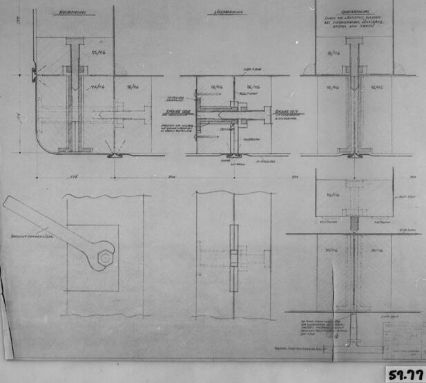
The image shows a black and white photograph of an engineering drawing or blueprint. The drawing includes multiple views of a mechanical design, likely a component or an assembly of parts, with various dimensions and annotations indicating sizes and specifications. There are overhead, side, and detail views illustrating the different parts of the component, with lines, figures, and alphanumeric text labeling the features. The drawing is framed by a black border and appears to be mounted or placed on a slightly larger background, with a number in the corner "52.77," which might refer to a figure number, sheet number, or identification code in a larger set of plans or documentation. It’s important to note that blueprints such as this one play a vital role in the manufacturing, engineering, and construction industries by providing detailed specifications for creating precise components or structures.
Created by gpt-4o-2024-05-13 on 2024-12-07
The image displays a technical drawing or blueprint contained within a black frame. The drawing includes various sections and elevations of a mechanical component or assembly, likely associated with engineering or construction.
Key features of the drawing include:
- Multiple detailed views of the component, displaying different aspects such as cross-sections or exploded views.
- Annotations and dimensions indicating measurements and specifications for manufacturing or assembly.
- Labels and notes providing additional instructions or descriptions for parts of the component.
- A recognizable image of a wrench or tool in the lower left section.
- A reference number "59.77" at the bottom of the frame.
Overall, the blueprint is a technical document meant to convey precise information for construction or manufacturing purposes.
Anthropic Claude
Created by us.anthropic.claude-3-5-sonnet-20241022-v2:0 on 2025-06-24
This image appears to be a technical engineering or architectural drawing showing various detailed cross-sections and mechanical components. The drawing is in black and white and appears to be a vintage or historical document. It contains multiple views of what seems to be some kind of structural or mechanical assembly, with precise measurements and annotations. The drawing is presented in a framed or mounted format, and includes both elevation and sectional views. There's a number visible at the bottom of the frame (59.77). The drawings show detailed construction or assembly information with different components carefully laid out to demonstrate how they fit together.
Created by claude-3-haiku-20240307 on 2024-12-07
The image appears to be an engineering or architectural drawing or schematic. It contains various technical diagrams, measurements, and annotations related to some kind of mechanical or structural design. The drawing seems to depict different views or cross-sections of a structure or device, with detailed dimensions and specifications provided. Overall, this image is a technical illustration or blueprint intended for engineering or construction purposes.
Created by claude-3-5-sonnet-20241022 on 2024-12-07
This image appears to be a technical engineering or architectural drawing showing various cross-sectional views and details. The drawing is in black and white and appears to be a vintage or historical document. It shows multiple detailed diagrams with measurements and annotations, possibly depicting some kind of mechanical or structural component. The drawings include both vertical and horizontal cross-sections, and there appears to be some German text labels on the document. The image has a dark border around it and appears to be photographed or scanned from an original document. There's a number visible at the bottom (59.77), which could be a reference or catalog number.
Meta Llama
Created by us.meta.llama3-2-11b-instruct-v1:0 on 2024-12-07
The image presents a black-and-white architectural drawing, showcasing a detailed design for a building or structure. The drawing is composed of various sections, each containing precise measurements and annotations, likely intended to guide the construction process.
Key Features:
- Drawing Composition: The drawing is divided into multiple sections, each focusing on a specific aspect of the building's design.
- Measurements and Annotations: The sections include precise measurements and annotations, indicating the intended use of the drawing for construction purposes.
- Black-and-White Format: The image is presented in a black-and-white format, which was common for architectural drawings prior to the widespread use of color technology.
- Framed Presentation: The drawing is framed within a black border, adding a touch of professionalism to the presentation.
- Background: The background of the image appears to be a light-colored surface, possibly a table or desk, providing a neutral backdrop for the framed drawing.
Overall Impression:
The image conveys a sense of professionalism and attention to detail, suggesting that the drawing was created by an experienced architect or designer. The use of precise measurements and annotations implies that the drawing was intended for practical application, such as guiding the construction of a building or structure.
Created by us.meta.llama3-2-90b-instruct-v1:0 on 2024-12-07
The image presents a technical drawing, likely an architectural or engineering blueprint, featuring a detailed design for a structure or component. The drawing is rendered in black ink on a white background, with various lines, shapes, and annotations that provide specific measurements and dimensions.
Key Features:
- Central Element: A prominent vertical element dominates the center of the drawing, possibly representing a column, beam, or other structural component.
- Annotations and Measurements: Numerous annotations and measurements are scattered throughout the drawing, indicating precise dimensions and specifications for the design.
- Geometric Shapes: Various geometric shapes, such as rectangles, triangles, and circles, are used to represent different components or features of the design.
- Lines and Arrows: Lines and arrows are employed to illustrate connections, relationships, and flow between different parts of the design.
Overall Impression:
The technical drawing appears to be a detailed and precise representation of a specific design or concept, likely created for purposes of construction, manufacturing, or analysis. The use of standardized symbols, notation, and measurement units suggests a professional or technical context, such as architecture, engineering, or product design.
Amazon Nova
Created by amazon.nova-lite-v1:0 on 2025-02-26
The image is a technical drawing or blueprint, which is a detailed representation of a structure or component, typically used in engineering and architectural contexts. The drawing is contained within a black frame, indicating it might be a part of a larger collection or document. The drawing itself is a combination of various lines, symbols, and annotations that are common in engineering and architectural plans.
At the center of the drawing, there appears to be a detailed section of a mechanical component, possibly a part of a machine or an apparatus. The component is depicted with various dimensions and annotations, suggesting it is intended for precise construction or assembly. The annotations include measurements in a unit that is not specified, but they are likely in millimeters or inches, common units in technical drawings.
The drawing also includes several cross-sectional views and detailed parts, indicating the complexity of the component. There are arrows and labels pointing to specific areas, which could be instructions or notes for the assembler or fabricator. The drawing is labeled with a number "51.77" at the bottom right corner, which could be a reference number or a part number.
The background of the drawing is plain and white, which helps to highlight the details of the drawing. The overall quality of the image suggests it is a high-resolution scan or a photograph of a physical drawing, rather than a digital creation.
In summary, the image is a technical drawing of a mechanical component, complete with dimensions, annotations, and cross-sectional views, intended for precise construction or assembly. The drawing is labeled with a reference number and is contained within a black frame, indicating it might be part of a larger document or collection.
Created by amazon.nova-pro-v1:0 on 2025-02-26
The image is a blueprint, which is a technical drawing used in construction or engineering. The blueprint is framed with a black border, and the paper appears to be old, with some signs of wear and tear. The blueprint consists of various sections, each depicting different parts of a structure or system. The sections include elevations, plans, and details, which are typically used to illustrate the dimensions, materials, and construction methods for a building or mechanical system. The blueprint also includes annotations and measurements, which are essential for the construction or maintenance of the structure or system.
Google Gemini
Created by gemini-2.0-flash-lite on 2025-04-28
The image is a technical drawing, likely an engineering or architectural blueprint, framed and viewed from above. The drawing is presented on a sheet of paper, which is then encased in a protective layer and framed with a black border.
The blueprint itself is rendered in black and white, with intricate lines, annotations, and measurements. It appears to depict various cross-sections and detailed views of mechanical components or structural elements. Several areas are labeled, possibly indicating specific features, materials, or instructions. There are also diagrams of tools, such as a wrench, and dimensions. The sheet includes a label reading "59.77" in the lower right corner.
Created by gemini-2.0-flash on 2025-04-28
Here's a description of the image:
The image is a black and white photograph of a framed technical drawing or blueprint. The drawing contains several views and sections of a mechanical component or system, rendered in a technical style with precise lines, dimensions, and annotations.
The top half of the drawing shows a series of sectional views, likely depicting the internal structure and assembly of a device. The sections appear to cut through various planes, revealing the arrangement of cylindrical shafts, housings, and other mechanical elements. Annotations and dimensions are visible, providing specific measurements and specifications.
The bottom half of the drawing features additional views, including a detailed sketch of a wrench or spanner tool. There are also further sectional views and diagrams, which could be related to the operation or installation of the mechanical system.
The overall impression is that of a meticulous and detailed engineering design. The drawing is set against a neutral background, framed in black, with the frame itself exhibiting some imperfections and wear. A label, possibly a catalog or reference number, is visible at the bottom right corner of the frame.
Mistral Pixtral
Created by us.mistral.pixtral-large-2502-v1:0 on 2025-04-28
The image depicts a framed technical drawing, likely an architectural or engineering blueprint. The drawing is detailed and includes various sections, dimensions, and annotations. Here is a breakdown of the key elements visible in the image:
Sections and Views:
- The drawing is divided into multiple sections, each representing different views or details of a structure or mechanism.
- There are front views, side views, and possibly cross-sectional views to illustrate internal components.
Dimensions and Measurements:
- The drawing includes precise measurements and dimensions, indicated by lines and numerical values.
- These measurements are crucial for the accurate construction or assembly of the depicted structure or mechanism.
Annotations:
- The drawing contains various annotations and labels, which provide additional information about the components and their functions.
- These annotations are written in a language that appears to be German, suggesting that the drawing might be from a German-speaking region or for a German-speaking audience.
Components:
- The drawing shows different components, such as pipes, valves, and structural elements.
- These components are depicted in detail, with specific parts labeled for clarity.
Framing:
- The drawing is framed in a simple, dark-colored frame, which helps to protect and display the document.
- The frame has a label at the bottom right corner with the number "59.77," which might be an identification or catalog number.
Overall, the image is a detailed technical drawing that provides comprehensive information for the construction or assembly of a specific structure or mechanism, with precise measurements and annotations to guide the process.
Qwen
Created by Qwen/Qwen2.5-VL-7B-Instruct on 2025-07-26
The image appears to be a technical drawing or blueprint. It contains multiple diagrams and cross-sectional views, likely of a mechanical or structural component. The drawings are labeled with various measurements and specifications, indicating different parts and their dimensions. The components seem to include cylindrical parts, a crankshaft-like element, and some mechanical fasteners or bolts. The diagrams are neatly labeled with part numbers and annotations, suggesting this is a detailed technical specification for a manufacturing or engineering project. The bottom right corner of the image has a number "51.77," which could be a revision or document code.
Created by Qwen/Qwen2.5-VL-72B-Instruct on 2025-07-26
This image is a technical drawing or blueprint, likely related to engineering or construction. It contains detailed views of a mechanical or structural component. The drawing includes multiple sections and elevations, annotated with measurements, dimensions, and technical specifications.
The top left section appears to show an elevation view of a cylindrical structure, possibly a tank or vessel, with various components such as pipes and fittings. The labels and dimensions indicate the size and placement of these elements.
The top right section provides a detailed cross-section of the structure, showing internal components and their arrangement. The annotations here likely describe the materials and construction methods used.
The bottom left section displays a side view of a mechanical part, possibly a handle or lever, with a hexagonal shape at one end. This view is labeled and dimensioned to provide precise fabrication details.
The bottom right section shows another cross-section, focusing on a different part of the structure or a related component. The annotations here provide additional technical information.
Overall, this blueprint is a comprehensive technical document used for manufacturing, installation, or maintenance purposes, ensuring that all necessary details are clearly communicated.
Text analysis
Amazon