Machine Generated Data
Tags
Color Analysis
Feature analysis
Amazon

| Document | 80% | |
Categories
Imagga
| text visuals | 99.8% | |
| paintings art | 0.1% | |
Captions
Microsoft
created on 2018-03-22
| a close up of text on a white background | 74.5% | |
| a close up of text on a white surface | 71.7% | |
| a close up of text on a black background | 67.5% | |
OpenAI GPT
Created by gpt-4 on 2025-03-06
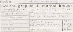
This image shows a series of architectural drawings or blueprints. The drawings outline different aspects of a building's design, including elevation views and section cuts. You can see detailed annotations and measurements that specify dimensions and structural components, such as doors and windows. In the bottom right corner, there is a title block with information suggesting that the blueprints were created by an architectural firm. The text in this title block indicates the names of the architects, the location of the firm, and possibly the date of the draft along with other project details such as sheet number and scale. It appears to be a professional and technical document used for the construction or design review of a building.
Created by gpt-4o-2024-05-13 on 2025-03-06
The image is a detailed architectural drawing on a large sheet of paper, likely a blueprint or plan for construction. The drawing contains technical annotations and precise measurements, illustrating the "North Elevation," "Section A-A," and "South Elevation" of a structure. The annotations and lines depict various structural elements such as plates, studs, sills, and foundations with measurements written alongside each component. The drawing includes labels and notes about materials and sizes, indicating components like "2X4 Studs" and "Concrete Block Foundation." There are detailed notes on the thickness of materials, such as "1 1/8” Ceiling" and "3/4” Plywood Ceiling." In the lower right corner, there is a title block with information about the architects, indicated as Walter Gropius and Marcel Breuer, associated architects based in Cambridge, Massachusetts. The project is named "Single Livin U Program Ermitage House & Urbanization Plats," and the drawing is dated October 25, 1950. The scale of the drawing is noted as "1/4”=1’-0”. The drawing is professional and appears to belong to an architect-engineering plan, showcasing the formal and precise nature of architectural documentation.
Anthropic Claude
Created by claude-3-haiku-20240307 on 2024-12-30
This image appears to be an architectural drawing or plan, showing multiple elevations and a section view of a structure. The drawing contains various technical details, measurements, and annotations describing the structure. It appears to be a design drawing created by the architectural firm "walter gropius & marcel breuer" for a project located in Cambridge, Massachusetts. The drawing provides a detailed technical representation of the planned structure, likely to aid in its construction.
Created by claude-3-5-sonnet-20241022 on 2024-12-30
This image appears to be an architectural drawing showing both North and South elevations of a building, along with a section detail labeled "SECTION A." The drawing is done in a technical architectural style with various measurements and annotations. It was created by Walter Gropius & Marcel Breuer Associated Architects from Cambridge, Massachusetts, as indicated in the title block at the bottom right corner of the sheet. The elevations show various construction details including what appears to be foundation elements, structural framing, and different building levels. The drawings contain numerous dimensional notations and construction notes. The sheet is numbered "12" and appears to be part of a larger set of architectural drawings. The style of the drawing is typical of mid-20th century architectural documentation, with clean lines and precise technical detailing. The drawing provides important construction information for builders to understand how the structure should be assembled from different viewing angles.
Meta Llama
Created by us.meta.llama3-2-11b-instruct-v1:0 on 2025-03-13
The image displays a technical drawing of a building's floor plan, likely created by architects Walter Gropius and Marcel Breuer. The drawing is on a beige background with black ink and appears to be hand-drawn. * **Title and Date** * The title of the drawing is not visible. * The date "Dec. 6, 1938" is written in the bottom-right corner. * **Floor Plan** * The floor plan is divided into sections labeled "North Elevation," "Section A-A," and "South Elevation." * Each section shows a different view of the building's layout, including rooms, doors, windows, and other architectural features. * The drawings are detailed and include measurements and notes in the margins. * **Architects' Names** * The names "Walter Gropius & Marcel Breuer" are written in the bottom-right corner, along with their title "associated architects" and the city "Cambridge, Mass." * **Other Text** * There are several other lines of text throughout the drawing, including measurements, notes, and possibly the names of other individuals involved in the project. Overall, the image provides a detailed view of the building's floor plan and suggests that it was created by two well-known architects, Walter Gropius and Marcel Breuer.
Created by us.meta.llama3-2-90b-instruct-v1:0 on 2025-03-13
The image presents a detailed architectural drawing of a building's elevation and section, likely created by Walter Gropius and Marcel Breuer. The drawing is divided into two main sections: the top half features a north elevation, while the bottom half displays a south elevation and a section A-A. **North Elevation:** * The north elevation is depicted in the top half of the drawing. * It includes various details such as windows, doors, and other architectural features. * The elevation is drawn to scale, with measurements and annotations provided for clarity. **South Elevation and Section A-A:** * The south elevation is shown in the bottom half of the drawing, adjacent to section A-A. * Section A-A provides a cross-sectional view of the building, revealing its internal structure and layout. * Both the south elevation and section A-A are also drawn to scale, with measurements and annotations included. **Additional Details:** * The drawing includes a title block in the bottom-right corner, which contains information about the architects, project name, and date. * The title block reads "Walter Gropius & Marcel Breuer" and lists the project as "Associated Architects, Cambridge, Mass." * The date "Dec 6 1938" is also included, indicating when the drawing was created. Overall, this architectural drawing provides a comprehensive view of the building's design, including its exterior elevations and internal structure. The level of detail and precision suggests that it was created for construction purposes or as part of a larger architectural project.
Amazon Nova
Created by amazon.nova-lite-v1:0 on 2025-01-13
This image is a page from an architectural drawing or blueprint. It contains detailed technical drawings and specifications for a building or structure. The page is divided into sections, with the top portion featuring a plan view or floor plan of the building, showing the layout of rooms, walls, and other structural elements. The middle section includes elevation drawings, which depict the exterior views of the building from different angles. The bottom section contains detailed notes, dimensions, and specifications for various components of the structure, such as beams, columns, and foundation details. The text and annotations provide information about materials, dimensions, and construction techniques. The image appears to be a professional architectural drawing used for planning and construction purposes.
Created by amazon.nova-pro-v1:0 on 2025-01-13
The image is a detailed architectural drawing on a white sheet of paper. The drawing consists of several sections, each labeled with text and numbers. The top section is labeled "2-3/4 PLATE," with a grid-like structure and annotations. Below it, there is a section labeled "North Elevation," which includes a detailed drawing of a building's north side, with measurements and annotations. The bottom section is labeled "South Elevation," with a similar detailed drawing of the building's south side. The drawing includes various annotations, measurements, and labels, such as "SECTION A," "1-2-1 PLATE," and "1-2-1 1/2 PLATE." The drawing appears to be a technical blueprint for a building, with precise measurements and details.
Text analysis
Amazon