Machine Generated Data
Tags
Color Analysis
Categories
Imagga
| text visuals | 99.9% | |
| paintings art | 0.1% | |
Captions
Microsoft
created on 2018-03-22
| a close up of text on a white background | 79.9% | |
| a close up of text on a black background | 74.9% | |
| a close up of text on a white surface | 74.8% | |
OpenAI GPT
Created by gpt-4o-2024-05-13 on 2025-03-07
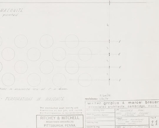
The image depicts architectural drawings and detailed plans for a building project by Ritchey & Mitchell, Register Architects, based in Pittsburgh, Pennsylvania, with involvement from associated architects Walter Gropius & Marcel Breuer, located in Cambridge, Massachusetts. The drawings are labeled and annotated in pencil with various measurements and details. The upper half of the drawing includes side and front elevations of portions of the building, marking different rooms, windows (marked "fixed skylight"), and doors, annotated with specific notes such as "two coat plaster," "Masonite," "Armstrong feature wall," and "clip stripe." Some notes indicate materials and finishes to be used, such as "paint finish." In the lower half, there are various sections of floor plans, with detailed layouts of bath and shower areas, including fixtures like toilets and basins. These sections are labelled with dimensions and specific details on construction elements. Towards the bottom of the image, there is a detailed, full-sized drawing showing perforations in a Masonite panel. The perforations are represented by circles drawn in a grid-like pattern, each with specific measurements. The sheet also contains a label box with project details: - The name "Ritchey & Mitchell, Register Architects, Pittsburgh, Penna" is prominently featured. - It notes revisions and the involvement of Walter Gropius & Marcel Breuer, associated architects located in Cambridge, Mass. - Further information about the project location, drawing number, date, and specific details is also included. The perforation detail at the bottom shows staggered circles, suggesting their use in creating a functional or aesthetic pattern in the building material.
Created by gpt-4 on 2025-03-07
This image depicts a set of architectural drawings or plans. It appears to be a detailed technical drawing that includes various sections and elevations. There are multiple annotations and measurements, indicating dimensions and materials, such as masonite or wood. In the lower center of the image, there are patterns of circles with the note "FULL SIZE DETAIL PERFORATIONS IN MASONITE," suggesting this part of the drawing shows details of perforations in a material called masonite. On the bottom of the drawing, there is some text that identifies the architects involved as "RITCHEY & MITCHELL REGISTERED ARCHITECTS PITTSBURGH, PENNA." and mentions "Walter Gropius & Marcel Breuer associated architects Cambridge, Mass." This reference to Gropius and Breuer, both notable figures in modern architecture, suggests that the drawing may be related to a significant project in architectural history. There is also a revisions block in the bottom right corner that typically contains dates and notes regarding changes made to the drawing over time. The drawing is presented in a very orderly and clean composition, typical of professional architectural plans.
Anthropic Claude
Created by claude-3-haiku-20240307 on 2024-12-31
This image appears to be an architectural drawing or plan. It contains multiple detailed floor plans and layouts, with measurements and annotations. The plans seem to be for a building or structure, though the specific purpose or function is not clearly indicated. The drawing includes a title "FLOOR PLANS", as well as the name "RITCHEY & MITCHELL, REGISTERED ARCHITECTS, PITTSBURGH, PENNA." at the bottom, suggesting these are architectural plans created by the firm Ritchey & Mitchell.
Created by claude-3-opus-20240229 on 2024-12-31
This image shows an architectural drawing or blueprint titled "Radial drive thru". It contains several diagrams and floor plans depicting the layout and dimensions of what appears to be a drive-through facility, likely for a restaurant or similar business. The plans include specifications and measurements. In the bottom right corner, there is a stamp indicating the drawing was created by "Ritchey & Mitchell Registered Architects" located in Pittsburgh, Pennsylvania.
Created by claude-3-5-sonnet-20241022 on 2024-12-31
This appears to be an architectural drawing or blueprint showing wall elevation details and perforation patterns. The top portion shows floor elevation plans with various measurements and specifications. Below that are smaller sectional views or details. At the bottom of the drawing is a pattern of circles arranged in rows, labeled as "perforations in Masonite." The drawing includes professional stamps and credits, including references to architects from Pittsburgh, PA. The overall style suggests this is a mid-century architectural document, likely from a commercial or institutional building project. The drawing is done in pencil or light ink on paper and includes technical specifications and dimensions throughout.
Meta Llama
Created by us.meta.llama3-2-11b-instruct-v1:0 on 2025-03-13
The image presents a technical drawing for a masonry project, featuring a detailed plan and elevation of the structure. The drawing is divided into three sections: a plan view, an elevation view, and a cross-section view. * **Plan View** + The plan view shows the layout of the masonry structure, including the location of walls, windows, and doors. + The drawing includes measurements and notes in the margins, indicating the scale and dimensions of the structure. * **Elevation View** + The elevation view shows the exterior of the masonry structure, including the height and width of the walls, as well as the location of windows and doors. + The drawing includes measurements and notes in the margins, indicating the scale and dimensions of the structure. * **Cross-Section View** + The cross-section view shows the internal structure of the masonry wall, including the location of the foundation, the wall itself, and the roof. + The drawing includes measurements and notes in the margins, indicating the scale and dimensions of the structure. The technical drawing provides a comprehensive overview of the masonry project, including the layout, elevation, and cross-section of the structure. The measurements and notes included in the margins provide additional information about the scale and dimensions of the structure, allowing for accurate construction and installation.
Created by us.meta.llama3-2-90b-instruct-v1:0 on 2025-03-13
The image presents a detailed architectural drawing of a building's floor plan, showcasing various rooms and spaces. The top section features four distinct floor plans, each with its own set of measurements and labels. The middle section is dedicated to a single room, labeled "KAIOTA STONE STOOL," which includes a detailed drawing of the room's layout and dimensions. The bottom section of the image appears to be a sketch or rough draft, featuring a series of circles and lines that may represent a design concept or idea. A small box in the bottom-right corner contains text that reads "RITCHEY & MITCHELL" and "REGISTERED ARCHITECTS PITTSBURGH, PENNA." This suggests that the drawing was created by an architectural firm based in Pittsburgh, Pennsylvania. Overall, the image provides a comprehensive view of a building's design and layout, highlighting the attention to detail and precision required in architectural planning.
Amazon Nova
Created by amazon.nova-lite-v1:0 on 2025-02-26
The image is a technical drawing of a floor plan, likely from an architectural or engineering project. The drawing is divided into several sections, each detailing different areas of a building. The top section shows a layout with various labeled rooms, including a "POOL," "DRESSING ROOM," and "NO. 108." Below this, there are more detailed floor plans with measurements and annotations. The drawing includes notes such as "PERFORATIONS IN MASONITE" and "MASONITE PAINTED," indicating materials and finishes. The bottom section has a detailed plan with circles and text, possibly indicating specific design elements or fixtures. The drawing is labeled with the names "Walter Gropius & Marcel Breuer" and "Ritchey & Mitchell," suggesting the involvement of these architects or firms in the project. The date "7/24/39" is also noted, indicating the time of the drawing's creation.
Created by amazon.nova-pro-v1:0 on 2025-02-26
The image is a detailed architectural blueprint of a building, specifically focusing on the interior layout and design. It appears to be a technical drawing with various sections and annotations. The blueprint is composed of multiple sections, each representing different parts of the building. The top section of the blueprint shows a floor plan with several rooms labeled and dimensions provided. The rooms include a pool, dressing room, and other unspecified spaces. Each room is outlined with precise measurements and annotations indicating the layout and dimensions. Below the floor plan, there are additional sections that provide more detailed views of specific areas. These sections include elevations and cross-sections, which offer a vertical perspective of the building's structure. The annotations in these sections include measurements, material specifications, and construction details. The bottom section of the blueprint contains a legend or key that explains the symbols and notations used throughout the drawing. This key is essential for understanding the various elements represented in the blueprint, such as wall types, door locations, and window placements. Additionally, the blueprint includes a title block with information about the project, including the project name, architect's name, and date of the drawing. This section also contains a revision history, indicating any changes made to the blueprint over time. Overall, the blueprint is a comprehensive document that provides a detailed overview of the building's design, including floor plans, elevations, and construction details. It is a crucial tool for architects, engineers, and contractors involved in the construction process, ensuring that all parties have a clear understanding of the project's requirements and specifications.
Text analysis
Amazon