Machine Generated Data
Tags
Color Analysis
Feature analysis
Amazon

| Document | 63.2% | |
Categories
Imagga
| text visuals | 99.9% | |
| paintings art | 0.1% | |
Captions
Microsoft
created by unknown on 2018-03-22
| a close up of text on a whiteboard | 76.3% | |
| a close up of a whiteboard | 74% | |
| close up of text on a whiteboard | 73.3% | |
Clarifai
created by general-english-image-caption-blip on 2025-05-03
| a photograph of a drawing of a plan for a house | -100% | |
OpenAI GPT
Created by gpt-4 on 2025-03-05
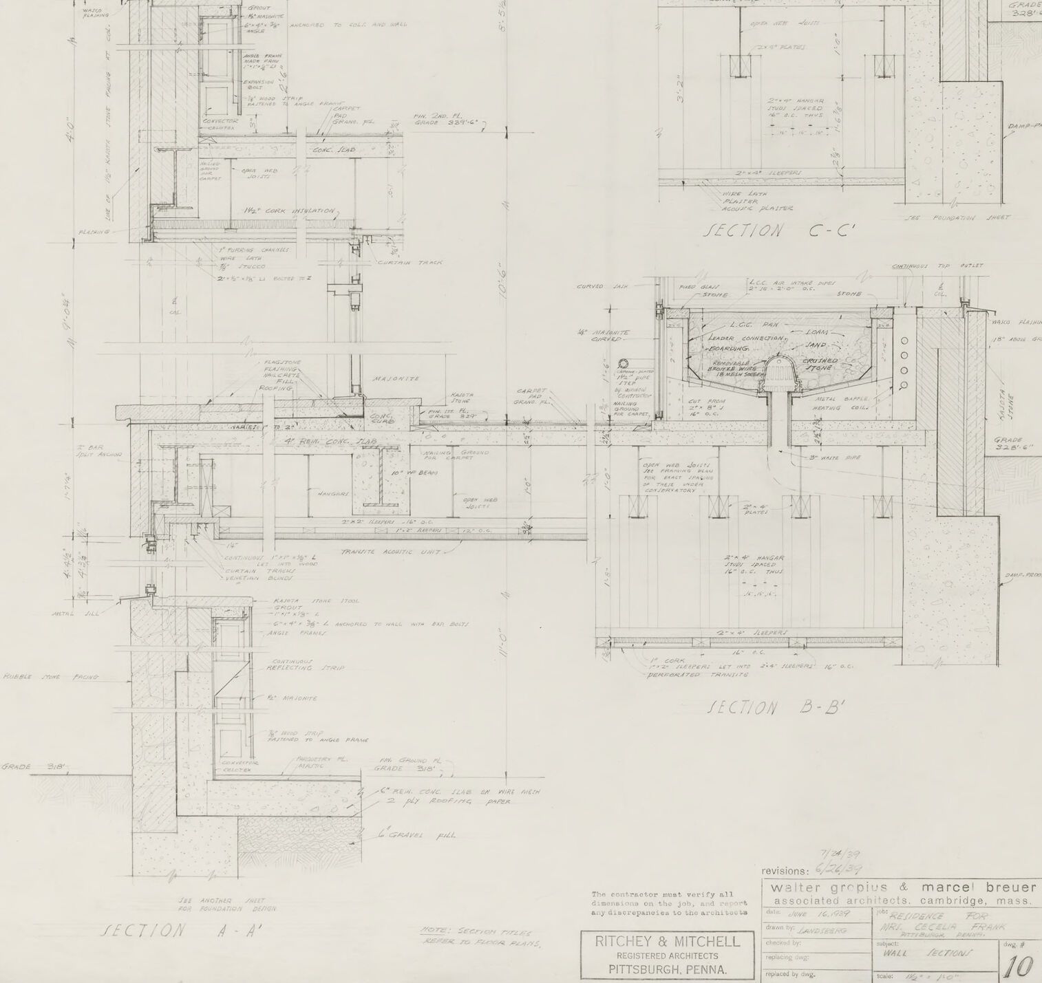
The image is of an architectural drawing or blueprint showing a series of detailed cross-sections of a building's construction. These sections illustrate the internal structure and design details of the building, including walls, floors, supports, and various architectural elements. Notes and dimensions are provided throughout the drawing to specify the materials, structural requirements, and sizes necessary for construction. The drawing is precise and technical, meant for use by architects, engineers, and construction professionals.
The names Walter Gropius and Marcel Breuer, who were notable figures in architecture, are mentioned on the drawing, suggesting their involvement in the project. The drawing also has a title block in the bottom right corner indicating the architectural firm or draftsperson and the location, which is Pittsburgh, Pennsylvania. The title block includes the names "Ritchey & Mitchell" which could be the architectural firm involved. It is dated and might include a revision history or job number, which are standard in architectural practice to keep track of changes and versions of the plans.
Created by gpt-4o-2024-05-13 on 2025-03-05
The image is an architectural drawing or blueprint which appears to be detailed construction sections of a building. These are precise technical diagrams that show cross-sectional views of a structure, indicating the dimensions, components, and relationships between different building elements.
Key features of this drawing include:
- Several vertical and horizontal sections labeled as "SECTION A-A," "SECTION B-B," and "SECTION C-C." These labels indicate different parts of the building being detailed.
- Numerous annotations and notes written in small, precise handwriting all over the drawing, likely detailing materials, measurements, construction techniques, and other important specifications.
- Each section includes elements such as walls, floors, windows, and structural components, all intricately drawn to scale.
- The bottom of the drawing has a title block containing information about the architects: Ritchey & Mitchell from Pittsburgh, Pennsylvania, and associated architects Walter Gropius & Marcel Breuer from Cambridge, Massachusetts. It also includes a reference number, "10," and the revisions with dates.
- The drawing uses various line styles, hatching, and shading to differentiate between different types of building materials and structural components.
The overall appearance is that of a professional, technical document used by builders and architects to accurately construct the building as designed.
Anthropic Claude
Created by claude-3-haiku-20240307 on 2024-12-30
The image appears to be an architectural engineering drawing or blueprint. It contains various detailed technical drawings, sections, and specifications for a construction project. The drawing appears to be part of the design process, with extensive notes, dimensions, and technical details included. The overall impression is that of a complex, meticulously planned construction project, likely for a building or structure of some kind.
Created by claude-3-opus-20240229 on 2024-12-30
The image shows an architectural drawing or blueprint of a building section. It includes various floor plans, elevations, and detailed drawings showing the layout and construction of what appears to be a residential or commercial structure. The plans feature dimensions, room labels, material notes, and cross-section views to provide a comprehensive representation of the building design. The drawing is rendered in black and white linework on a textured paper background, giving it a vintage or historical quality typical of hand-drafted architectural plans before the widespread adoption of computer-aided design (CAD).
Created by claude-3-5-sonnet-20241022 on 2024-12-30
This image appears to be an architectural drawing showing detailed section views of what seems to be interior architectural details. The drawing includes three different sections labeled as "SECTION A-A", "SECTION B-B", and "SECTION C-C". These are technical drawings with precise measurements and annotations, showing various construction details like wall assemblies, fixtures, and material specifications.
The drawings are done in a professional architectural style, with fine lines and detailed dimensions. At the bottom of the sheet, there's a title block indicating this is from "Walter Gropius & Marcel Breuer" and "Ritchey & Mitchell" architects from Pittsburgh, Pennsylvania.
The sections appear to be showing complex interior details, possibly of built-in furniture or architectural features, with careful attention to joints, materials, and assembly methods. The drawing is executed in pencil on what appears to be drafting paper, typical of mid-20th century architectural documentation.
The level of detail suggests this is a working drawing meant for construction purposes rather than a conceptual sketch, with specific instructions and measurements for builders to follow.
Meta Llama
Created by us.meta.llama3-2-11b-instruct-v1:0 on 2025-03-12
The image presents a detailed architectural blueprint for a building, showcasing various rooms and spaces. The blueprint is divided into sections, each labeled with a letter or number, and includes measurements and notes in the margins. The rooms are depicted in a two-dimensional format, with walls, doors, windows, and other features clearly illustrated.
Key Features:
- Section Labels: The blueprint is divided into sections, each labeled with a letter or number (e.g., "SECTION A-B").
- Measurements and Notes: Measurements and notes are provided in the margins, likely for construction purposes.
- Room Layout: The rooms are depicted in a two-dimensional format, with walls, doors, windows, and other features clearly illustrated.
- Architectural Style: The blueprint appears to be from the mid-20th century, based on the style and layout of the rooms.
- Scale: The scale of the blueprint is not explicitly stated, but it appears to be a detailed and accurate representation of the building's design.
Purpose:
The purpose of this blueprint is likely to provide a detailed and accurate representation of the building's design for construction or renovation purposes. It may have been used by architects, engineers, or contractors to plan and execute the building's construction.
Conclusion:
In conclusion, the image presents a detailed architectural blueprint for a building, showcasing various rooms and spaces. The blueprint is divided into sections, includes measurements and notes, and features a two-dimensional layout of the rooms. The purpose of this blueprint is likely to provide a detailed and accurate representation of the building's design for construction or renovation purposes.
Created by us.meta.llama3-2-90b-instruct-v1:0 on 2025-03-12
The image presents a detailed architectural blueprint, likely created for a building or structure. The blueprint is divided into sections, each labeled with letters and numbers, indicating different areas of the design.
Key Features:
- Section Labels: The blueprint features section labels such as "SECTION C-C" and "SECTION D-D," which suggest that the design is being presented from various angles and perspectives.
- Architectural Details: The blueprint includes intricate details about the architecture, including doorways, windows, staircases, and other structural elements.
- Scale and Measurements: The blueprint appears to be drawn to scale, with measurements and dimensions provided throughout the design. This suggests that the blueprint is intended for use in construction or renovation projects.
- Architectural Firm: The bottom-right corner of the blueprint features the name of an architectural firm, "Ritchey & Mitchell," along with their location, "Pittsburgh, Pennsylvania." This indicates that the firm was responsible for creating the design and may have been involved in the construction process.
Conclusion:
In summary, the image depicts a detailed architectural blueprint created by Ritchey & Mitchell, an architectural firm based in Pittsburgh, Pennsylvania. The blueprint provides a comprehensive overview of the design, including section labels, architectural details, scale and measurements, and the firm's information.
Amazon Nova
Created by amazon.nova-pro-v1:0 on 2025-01-11
The image is a technical drawing on a white background. The drawing consists of several sections, each labeled with a letter (A-C) and a number. The sections depict various parts of a building's structure, including walls, floors, and possibly roofs. The drawing is detailed, with lines and annotations indicating measurements, materials, and construction methods. The overall design appears to be a multi-story building with a complex layout.
Created by amazon.nova-lite-v1:0 on 2025-01-11
This image is a detailed architectural drawing, likely from a construction or renovation project. The drawing is labeled "SECTION A-A" and "SECTION B-B," indicating that it is a cross-sectional view of a building or structure. The drawing is divided into two main sections, with the left section labeled "SECTION A-A" and the right section labeled "SECTION B-B." Each section contains multiple lines and measurements, indicating the dimensions and layout of the structure. The drawing also includes labels and notes, such as "WALL," "FLOOR," and "CEILING," which provide additional information about the structure's components. The drawing appears to be a technical document used by architects, engineers, and construction professionals to plan and execute a building project.
Google Gemini
Created by gemini-2.0-flash-lite on 2025-04-29
Here's a description of the image:
The image is a detailed architectural drawing, likely a blueprint or technical drawing. It appears to be a cross-section of a building, showing the internal structure and materials used in its construction.
Here's a breakdown of what's visible:
- Sections: The drawing is divided into sections labeled A-A', B-B', and C-C'. These labels indicate the different areas the cross-sections were taken from.
- Details: It features numerous lines, annotations, and measurements. The drawing shows the intricate details of the building's components, including walls, floors, ceilings, windows, and any structural elements.
- Materials: The different materials and construction methods are indicated using various line styles and cross-hatching.
- Scale: Measurements are present, which help in understanding the size and proportions of the building's components.
- Text: There is text throughout the drawing which contains information about dimensions, materials, and potentially notes on the design and construction.
- Title Block: A title block at the bottom of the drawing identifies the architects (Ritchey & Mitchell), the project (The building, the sheet's number, revisions, and sometimes dates.) and the overall context of the drawing.
Overall, it's a technical document intended for use by builders, engineers, and other professionals involved in the construction of the building.
Created by gemini-2.0-flash on 2025-04-29
Here is a description of the image:
The image is a blueprint of building sections, presented in a technical drawing style. It features multiple cross-sectional views labeled "SECTION A-A'," "SECTION C-C'," and "SECTION B-B'." Each section provides detailed architectural and structural information, including dimensions, materials, and construction techniques. Annotations are present throughout the drawing, offering additional details and specifications. The blueprint bears the name "RITCHEY & MITCHELL, REGISTERED ARCHITECTS, PITTSBURGH, PENNA" along with the revisions as "walter groplus & marce breuer associates architects, cambridge, mass". The page number is indicated as "10". Overall, the image conveys a sense of precision and technical expertise, essential for architectural design and construction.
Mistral Pixtral
Created by us.mistral.pixtral-large-2502-v1:0 on 2025-05-26
The image is an architectural drawing, specifically a detailed section drawing of a building. It is a technical illustration showing cross-sectional views of the building's structure, highlighting various elements such as walls, floors, ceilings, and other structural components. The drawing includes several sections labeled "Section A-A", "Section B-B", and "Section C-C", each providing a different perspective or cut through the building.
Key features of the drawing include:
Sections: The drawing is divided into three main sections, each labeled with a different letter (A, B, C). These sections show the internal structure of the building from different angles.
Details: Each section includes detailed measurements, annotations, and labels indicating the materials, dimensions, and specific components of the structure. These details are crucial for construction and understanding the building's layout.
Scale: The drawing likely includes a scale to ensure accurate interpretation of the dimensions.
Architectural Firm: The drawing is credited to "Walter Gropius & Marcel Breuer, Architects, Cambridge, Mass." and "Ditchett & Mitchell, Associate Architects, Pittsburgh, Penna." This indicates the collaboration between these firms on the project.
Date: The drawing is dated "10/27/58," suggesting it was created on October 27, 1958.
Purpose: Such drawings are typically used for construction purposes, providing builders and engineers with precise information about the building's design and structure.
Overall, the image is a comprehensive and detailed architectural section drawing, essential for the construction and understanding of the building's internal structure.
Text analysis
Amazon