Machine Generated Data
Tags
Color Analysis
Categories
Imagga
| text visuals | 99.7% | |
| paintings art | 0.3% | |
Captions
Microsoft
created on 2018-03-22
| a close up of text on a whiteboard | 71.8% | |
| a close up of a whiteboard | 70.6% | |
| close up of text on a whiteboard | 69.1% | |
OpenAI GPT
Created by gpt-4 on 2024-12-16
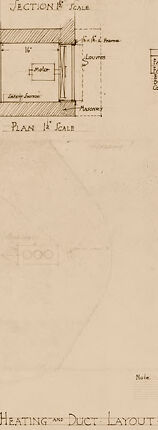
The image depicts a set of architectural or engineering drawings and diagrams. These documents are likely plans for a building's heating and duct layout, as indicated by the label at the bottom of the image. The paper appears aged, with some discoloration, suggesting that the drawing might be old. There are several components to the drawing: - To the right, there is a vertical section drawing labeled "Section & Scale," which shows the profiles of different ductwork components or possibly the interior of a wall indicating how ducting is arranged vertically. - The central part of the image features a more detailed plan diagram with numerous annotations. These annotations likely describe the dimensions, pathways, and components of the heating and duct system. There is a label "Plan & Scale" indicating this is a top-down view. - On the left-hand side, there is a larger, less detailed plan showing the overall layout of the duct system within a building or complex of rooms. - Below the main diagrams and plans, there is a title that reads "Heating & Duct Layout." - There are various notes and labels throughout the drawings, providing specifications, dimensions, and other technical data. - The bottom right corner contains some written text with potentially the name of an individual or company, perhaps responsible for the creation of the drawings, and additional details related to the document, such as a job number and other references. The image does not show all the finer details or annotations clearly due to the resolution, but overall, it provides an insight into the kind of meticulous planning that goes into designing building infrastructure.
Created by gpt-4o-2024-05-13 on 2024-12-16
The image depicts a technical drawing or blueprint labeled "Heating and Duct Layout." This architectural or engineering drawing includes several schematic views and sections, detailing the layout of heating and air duct systems. Key elements of the blueprint include: 1. **Section Views**: - There is a sectional view labeled "SECTION A," which illustrates the cross-sectional details of the heating and duct system, showing dimensions and various components. 2. **Plan Views**: - "PLAN A" is a top-down view of the duct layout, detailing the positioning and routing of ducts within the building. - Another plan view provides additional perspectives on the layout, with lines and arrows indicating the paths the ducts take through the space. 3. **Annotations and Labels**: - The drawing includes numerous handwritten annotations providing specifications, measurements, and notes on materials and connections within the system. - There is a "Fan Schedule" table, listing different parts (such as Fans) and their specifications, including quantity, size, and capacity. 4. **Technical Information**: - The border of the drawing contains information about the architects or engineers responsible for the drawing, including a firm name (Bumby & Mitchell). - The bottom right corner includes a title block with details like project number, date, and possibly the drafter's initials. The drawing is a detailed technical document used for planning, installing, or maintaining a building's heating and ventilation system.
Anthropic Claude
Created by claude-3-haiku-20240307 on 2024-12-16
This image appears to be an engineering or architectural blueprint or diagram. It contains technical drawings, measurements, and annotations related to a heating and duct layout or system. The diagram includes a cross-section view, plan view, and other detailed specifications and measurements. This seems to be a technical document or schematic related to the design or construction of a heating system or ductwork.
Created by claude-3-5-sonnet-20241022 on 2024-12-16
This appears to be an architectural or engineering drawing showing a heating and duct layout plan. The image contains several technical sketches including: 1. A section view at the top showing construction details 2. A plan view in the middle showing room layout and duct positioning 3. A larger schematic drawing at the bottom showing the complete heating duct layout The drawing is done in a vintage or historical style, appearing to be hand-drawn on aged paper with a sepia or brownish tone. There are various notations and measurements written throughout the drawing, and the title "HEATING and DUCT LAYOUT" is clearly visible at the bottom of the page. The drawing includes various technical details like duct sizes, directional flows, and construction specifications typical of HVAC system planning documents.
Meta Llama
Created by us.meta.llama3-2-11b-instruct-v1:0 on 2024-12-16
The image presents a detailed, hand-drawn diagram of a heating and duct layout, showcasing the intricate design and specifications of the system. The diagram is divided into several sections, each providing a unique perspective on the layout. * **Title and Layout** * The diagram is titled "Heating and Duct Layout" in the bottom center. * The layout is divided into three main sections: a top section, a middle section, and a bottom section. * **Top Section** * The top section appears to be a floor plan view of the building, showing the location of various rooms and spaces. * The section includes labels and annotations indicating the location of heating vents, ductwork, and other components. * **Middle Section** * The middle section is a cross-sectional view of the ductwork and heating system. * It shows the layout of the ducts, including their size, shape, and location within the building. * The section also includes labels and annotations indicating the type of duct material used, the airflow rate, and other relevant details. * **Bottom Section** * The bottom section appears to be a detailed view of a specific area of the ductwork or heating system. * It includes labels and annotations indicating the location of various components, such as valves, fittings, and sensors. * **Labels and Annotations** * Throughout the diagram, there are numerous labels and annotations providing additional information about the layout and components. * These labels and annotations include measurements, materials, and other relevant details. * **Overall** * The diagram provides a comprehensive overview of the heating and duct layout, including its design, components, and specifications. * It is likely that this diagram was created by an architect, engineer, or other professional involved in the design and installation of the heating system.
Created by us.meta.llama3-2-90b-instruct-v1:0 on 2024-12-16
The image presents a detailed blueprint of a heating and duct layout, showcasing various sections and plans. The title "Heating and Duct Layout" is prominently displayed at the bottom center of the page. **Key Features:** * **Section A-Ale:** A section view of the heating system, providing a detailed look at the components and their relationships. * **Plan 1st Floor:** A floor plan showing the layout of the heating system on the first floor, including the location of vents, ducts, and other equipment. * **Elevation:** An elevation view of the heating system, providing a side-on perspective of the components and their relationships. * **Section B-B:** Another section view of the heating system, offering a different perspective on the components and their relationships. * **Plan 2nd Floor:** A floor plan showing the layout of the heating system on the second floor, including the location of vents, ducts, and other equipment. **Additional Details:** * The blueprint includes various notes and labels, providing additional information about the heating system and its components. * The background of the image is a light brown color, with a subtle texture that gives it a vintage feel. Overall, the image provides a comprehensive overview of the heating and duct layout, making it an essential tool for architects, engineers, and contractors working on building projects.
Amazon Nova
Created by amazon.nova-lite-v1:0 on 2025-02-27
This image shows a page from a construction document, featuring architectural and mechanical plans for a building. The page is divided into sections, each with different types of diagrams and notes. The top section displays a vertical cross-section labeled "SECTION B SCALE," showing the structural layout of a building with details about materials and dimensions. Below this, there is a floor plan labeled "PLAN 1' SCALE," illustrating the layout of the building's interior spaces. The lower part of the page contains a heating and duct layout diagram, detailing the HVAC system with specifications and dimensions. The document is filled with technical drawings, measurements, and annotations, typical of construction blueprints.
Text analysis
Amazon