Machine Generated Data
Tags
Color Analysis
Categories
Imagga
| text visuals | 99.9% | |
Captions
Microsoft
created on 2018-03-22
| a whiteboard with black text | 82.8% | |
| a whiteboard with black text on a white surface | 77.4% | |
| a whiteboard with black text on a white background | 77.3% | |
OpenAI GPT
Created by gpt-4 on 2025-03-08
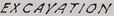
The image appears to be a technical drawing or plan, likely an architectural floor plan, due to the outlined shapes that resemble rooms and spaces. The plan is composed of dashed lines creating several connected rectangular shapes with numerical labels, possibly indicating room numbers or dimensions. On the top right of the plan, there is an isolated rectangular shape labeled "Garage," indicating it is a separate structure from the main plan. In the bottom portion of the image, there is a block of text that reads as follows: "MRS. CECILIA K. FRANK REM. PLAN & ESTIMATES FOR PLUMBING STATE OF NORTH CAROLINA DEPT. OF JUSTICE RALEIGH, N. S." [Some text is illegible] "WM. H. DEITRICK & CO., ARCHITECTS RALEIGH, N S" [Some text is illegible] "C-29,776C Draw. No. 6581" This text implies that the plan was prepared for someone named Mrs. Cecilia K. Frank and involves remodeling plans and estimates for plumbing, possibly for a state government project in North Carolina. The mention of Wm. H. Deitrick & Co. suggests the name of the architectural firm responsible for the drawing. The codes at the bottom likely identify the project number and drawing number for internal or archival tracking. The overall image is dominated by the large expanse of white space with the technical drawing positioned toward the left side.
Created by gpt-4o-2024-05-13 on 2025-03-08
The image is a technical drawing or blueprint. It appears to be a plan related to property development or land survey, indicating the "State of Rough Excavation" as of June 27, 1938. Key elements include: 1. A layout of different areas or structures represented by dashed lines. 2. Various sections labeled with numbers and descriptions such as "376," "372," "345," "343" for individual sections. 3. A specific area labeled "Garage" with dimensions "321.5" shown. 4. Other notable annotations are lines labeled "Line of Vacant Lot," "Line of Article 4," "Line of Article 3," etc. 5. The lower right corner of the drawing includes additional information: - The client name: "Mrs. Cecelia K. Frank." - Detailed description: "Plan Showing State of Rough Excavation State as of June 27, 1938." - Scale details: "Scale 1'-0" = 1/8"" - Date: "Dated June 27, 1938" - Created by: "Blue Delphit Inc, Engineers and Surveyors, Pittsburgh PA" - Drawing number: "C-2597-C" - Reference number: "Dwg. No. 6581" The drawing is mainly concentrated on the left side of the sheet, leaving a large portion of blank space on the right. The precise details and measurement scales suggest it is used for construction planning, surveying, or landscaping purposes.
Anthropic Claude
Created by claude-3-haiku-20240307 on 2024-12-30
This image appears to be a floor plan or architectural diagram. It shows the layout of a building or structure, with various rooms, dimensions, and labels indicated. The plan includes a garage and other designated spaces, but does not contain any human faces or identifiable individuals. The focus of the image is the technical details and design of the building layout.
Created by claude-3-5-sonnet-20241022 on 2024-12-30
This image appears to be an architectural floor plan or site survey drawing. It shows a layout with dashed lines indicating different sections or rooms, with some numerical measurements noted. There's a garage structure connected to what seems to be a main building via a pathway or corridor. The drawing is quite simple and done in a technical style with thin lines. At the bottom of the drawing, there is text that appears to be title block information including what looks like a date (June 22, 1939) and some reference numbers. The overall drawing is rendered in black and white on what appears to be drafting paper or similar archival material.
Meta Llama
Created by us.meta.llama3-2-11b-instruct-v1:0 on 2025-03-15
The image presents a detailed architectural plan for a house, showcasing its layout and design. The plan is rendered in black and white, with various rooms and spaces clearly labeled. **Key Features:** * **Room Labels:** Each room is assigned a unique number, allowing for easy identification and reference. * **Dimensions:** The plan includes measurements for each room, providing a sense of scale and proportion. * **Door and Window Locations:** The placement of doors and windows is carefully marked, ensuring that they are strategically positioned to maximize natural light and ventilation. * **Floor Plan:** The plan is divided into distinct sections, including a living room, kitchen, dining area, bedrooms, and bathrooms. * **Architectural Style:** The design appears to be a mix of modern and traditional elements, with clean lines, minimal ornamentation, and an emphasis on functionality. **Additional Details:** * **Scale:** The plan is drawn to a scale of 1/8 inch = 1 foot, allowing for accurate measurements and calculations. * **Date:** The plan is dated June 22, 1939, indicating that it was created during a specific time period. * **Architect's Signature:** Although the architect's signature is not visible, it is likely that the plan was created by a professional architect or designer. **Conclusion:** The architectural plan presented in the image provides a comprehensive overview of the house's design and layout. The inclusion of room labels, dimensions, and door and window locations ensures that the plan is both functional and aesthetically pleasing. The mix of modern and traditional elements suggests that the architect aimed to create a unique and timeless design. Overall, the plan is a valuable resource for anyone interested in understanding the intricacies of architectural design.
Created by us.meta.llama3-2-90b-instruct-v1:0 on 2025-03-15
The image depicts a hand-drawn floor plan of a building, likely created for architectural or construction purposes. The plan is drawn on a light gray background with black lines and text. **Key Features:** * **Floor Plan:** The floor plan is drawn in the lower left corner of the image, occupying approximately one-quarter of the space. It features various rooms and spaces, including a garage, living room, dining room, kitchen, bedrooms, and bathrooms. * **Room Labels:** Each room is labeled with its corresponding name or function, such as "LIVING ROOM" or "BEDROOM." * **Dimensions:** The plan includes dimensions for each room, providing measurements in feet and inches. * **Scale:** A scale is provided at the bottom of the plan, indicating that 1/8 inch represents 1 foot. * **Title Block:** A title block is located at the bottom of the image, containing information about the project, including the name of the architect or designer, the date, and the project number. * **Border:** The image has a thin border around the edges, which may be part of the original document or added during scanning or printing. **Overall Impression:** The image appears to be a professional architectural drawing, likely created for a residential building project. The level of detail and accuracy suggests that it was intended for use in construction or renovation work.
Amazon Nova
Created by amazon.nova-lite-v1:0 on 2025-01-12
The image is a technical drawing of a floor plan, likely for a building. The drawing is titled "MARS CECILIA K. FRANK" and is dated June 20, 1999. The drawing includes various measurements and labels, such as "Scale 1/10" and "C-2972-C, Dry. No. 6561". The floor plan includes a garage, a line of entrances, and a line of exits. The drawing also includes a table with measurements and labels, such as "317.6", "312.8", and "316.3". The drawing is on a white background and appears to be a technical drawing used for construction or architectural purposes.
Created by amazon.nova-pro-v1:0 on 2025-01-12
The image shows a white architectural blueprint on a white background. It is a detailed plan of a building with various rooms and spaces. The blueprint includes dimensions, labels, and annotations. It has a rectangular shape with a few irregular shapes inside. The blueprint includes a legend, a title, and a date. The title reads "MRS. CECILI'S K. FRANK PLAN, PLAIN SNOWING STATE OF ROUGH EXCAVATION AT DATE OF JUNE 20-1939."
Text analysis
Amazon