Machine Generated Data
Tags
Color Analysis
Feature analysis
Amazon
Clarifai

Clarifai
| Whiteboard | 46.5% | |
Categories
Imagga
created on 2018-03-22
| text visuals | 99.9% | |
| paintings art | 0.1% | |
Captions
Microsoft
created by unknown on 2018-03-22
| a close up of text on a whiteboard | 75.2% | |
| a close up of a whiteboard | 72.3% | |
| close up of text on a whiteboard | 72.2% | |
Clarifai
No captions written
Salesforce
Created by general-english-image-caption-blip on 2025-05-11
a photograph of a drawing of a plan for a house
Created by general-english-image-caption-blip-2 on 2025-06-27
a drawing of a building with a plan and elevation
OpenAI GPT
Created by gpt-4 on 2025-03-07
The image shows an architectural drawing or blueprint. The drawing is detailed and appears to be a cross-sectional elevation as it shows a vertical slice through a building, revealing the interior structure, different levels, and spatial relationships between them. The various sections and components of the building are clearly labeled with dimensions and notes indicating materials or construction details. Architectural features such as windows, doors, and possibly furniture arrangements or built-ins can be discerned.
The drawing includes text, which is too small to read in the provided image but would typically identify the name of the project, scale, architects, dates, and other relevant information. The overall presentation is precise and technical, which is characteristic of architectural plans used for construction and documentation of design intent. There are indications of handwriting and manual drafting, suggesting that this is not a computer-generated image but rather one that was likely created with traditional drafting tools.
Created by gpt-4o-2024-05-13 on 2025-03-07
This image depicts a detailed architectural elevation drawing of a building. The blueprint is meticulously annotated with measurements, design notes, and specifications for various features of the structure. It includes elements such as windows, doors, and other architectural details.
The drawing is generated by the architectural firms, "Ritchey & Mitchell" located in Pittsburgh, Pennsylvania, in collaboration with "Walter Gropius & Marcel Breuer Associates Architects." The title block at the bottom right corner contains essential information like the project's name, individual responsibilities, and other technical details to guide the construction process.
The plan outlines the north-east elevation of the building with a smaller section view to the right. The drawing uses thin, precise lines and often includes dimensions and labels for clarity. The annotations provide further information on materials and construction techniques, ensuring accurate translation from blueprint to final structure.
Anthropic Claude
Created by us.anthropic.claude-3-5-sonnet-20241022-v2:0 on 2025-06-24
This is an architectural drawing or blueprint showing a sectional elevation view of a building. The drawing appears to be quite detailed, with various levels and spaces clearly delineated. It's rendered in a traditional architectural drafting style with thin lines on what looks like paper or vellum. The drawing includes measurements, annotations, and technical details typical of professional architectural documentation. At the bottom of the sheet, there's a title block with what appears to be project information and architect details. The overall composition shows both interior and exterior elements of the structure in cross-section, allowing viewers to understand the vertical relationships between different spaces in the building. The drawing style suggests this is likely from the mid-20th century, given its hand-drawn nature and presentation format.
Created by claude-3-haiku-20240307 on 2024-12-29
The image appears to be an architectural blueprint or technical drawing. It shows a detailed plan with various structural elements, dimensions, and annotations. The drawing seems to depict the layout and design of a building or structure, likely for construction or renovation purposes. The overall composition consists of various orthographic views, sections, and details that provide a comprehensive visual representation of the intended design.
Created by claude-3-5-sonnet-20241022 on 2024-12-29
This is an architectural drawing or blueprint, specifically a section view/elevation drawing. It appears to be for a residential or commercial building project, showing the interior cut-through view of the structure with various levels, walls, and spaces detailed. The drawing is done in a technical style with fine lines and includes dimensions and annotations. In the bottom right corner, there's a title block with what appears to be project information and architectural firm details. The drawing is primarily in grayscale and shows multiple floor levels with various room configurations and structural elements. It's a detailed technical document that would be used during the construction or planning phase of a building project.
Meta Llama
Created by us.meta.llama3-2-11b-instruct-v1:0 on 2025-03-14
The image presents a detailed architectural drawing, showcasing a building's floor plan and elevation. The drawing is rendered in black ink on white paper, with various symbols and notations indicating different features and dimensions.
- Floor Plan:
- The floor plan is drawn in a two-dimensional perspective, with walls, doors, windows, and other architectural elements clearly labeled.
- The drawing includes measurements and notes in the margins, providing additional context for the design.
- The floor plan appears to be for a residential or commercial building, with multiple rooms and spaces.
- Elevation:
- The elevation drawing shows the exterior of the building, including the facade, roof, and any notable features such as columns or archways.
- The elevation is drawn in a similar style to the floor plan, with clear labels and measurements.
- The elevation suggests that the building has a symmetrical design, with a central entrance and evenly spaced windows.
- Symbols and Notations:
- Throughout the drawing, various symbols and notations are used to indicate different features and dimensions.
- These symbols may include arrows, lines, and other markings that provide additional information about the design.
- The notations include measurements, such as room sizes and door widths, as well as notes about materials and construction methods.
- Paper and Ink:
- The drawing is rendered in black ink on white paper, providing a clear and legible image.
- The paper appears to be of high quality, with a smooth texture that allows for precise lines and details.
- The ink is dark and consistent, with no visible smudging or bleeding.
In summary, the image presents a detailed architectural drawing of a building, showcasing its floor plan and elevation. The drawing is rendered in black ink on white paper, with various symbols and notations providing additional context for the design. The floor plan and elevation suggest a symmetrical design with multiple rooms and spaces, while the symbols and notations offer insight into the building's features and dimensions.
Created by us.meta.llama3-2-90b-instruct-v1:0 on 2025-03-14
This image presents a detailed architectural blueprint, likely created for a residential or commercial building project. The blueprint is rendered in black ink on a white background, with a grid pattern and various symbols and notations that provide information about the design and construction of the building.
The blueprint appears to be a floor plan, showing the layout of rooms, corridors, and other features within the building. It includes measurements and dimensions, as well as notes on materials and construction methods. The level of detail suggests that this is a working drawing, intended for use by architects, engineers, and contractors during the design and construction process.
Overall, this image provides a fascinating glimpse into the world of architecture and construction, highlighting the importance of careful planning and attention to detail in creating functional and aesthetically pleasing buildings.
Amazon Nova
Created by amazon.nova-lite-v1:0 on 2025-01-10
The image is a detailed architectural drawing of a residential building. The drawing appears to be a floor plan or a section view, showing various levels of the structure. It includes labels and dimensions indicating different areas and features of the building. The drawing is technical, with precise lines and annotations, suggesting it is a part of the construction documents for the project. The style and content of the drawing indicate that it is from the mid-20th century, possibly the 1950s or 1960s.
Created by amazon.nova-pro-v1:0 on 2025-01-10
The image depicts an architectural drawing of a building. The drawing is on a white background and appears to be a blueprint for a residential building. The blueprint is divided into several sections, each representing a different part of the building. The sections are labeled with numbers and letters, indicating the different rooms and areas of the building. The drawing includes measurements, dimensions, and other details that are essential for the construction of the building.
Google Gemini
Created by gemini-2.0-flash on 2025-05-12
Here's a description of the image:
The image is a technical architectural drawing, likely a blueprint or elevation, depicting a multi-level building design. The style suggests mid-20th century modern architecture.
Key Details:
- Layout: The drawing shows a complex arrangement of levels and structures, possibly terraced into a hillside. There are multiple tiers, with what appear to be walls, windows, and balconies.
- Annotations: The drawing is heavily annotated with handwritten notes, dimensions, and technical specifications.
- Materials: The style of the building seems to incorporate modernist principles, possibly using concrete, glass, and steel.
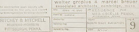
- Title Block: In the lower right corner is a title block with text indicating "Walter Gropius & Marcel Breuer, Associated Architects, Cambridge, Mass." and "Residence for Mrs. Cecilia Frank." It is titled "North East Elevation" and has the drawing number "9". The drawing also indicates that it was created and revised several times throughout the year 1949.
- Architect Firm: The architectural firm listed in the bottom left corner is "Ritchey & Mitchell, Registered Architects, Pittsburgh, Penna."
Overall Impression:
The image captures a snapshot of the design process for a significant modern residence, showcasing the precision and detail involved in architectural planning.
Created by gemini-2.0-flash-lite on 2025-05-12
This is an architectural drawing, specifically an elevation view of a building. It is a detailed hand-drawn blueprint with precise measurements, annotations, and labels. The perspective appears to be a side view of the building, revealing its facade with windows, roof lines, and possibly details of the landscaping or surrounding structures. The style of drawing is technical, indicating a professional architectural plan. The paper has aged, giving it a vintage feel. The bottom right corner shows the architect's name, and title.
Mistral Pixtral
Created by us.mistral.pixtral-large-2502-v1:0 on 2025-05-29
The image is a detailed architectural blueprint or floor plan of a building. Here are some key observations:
Layout and Design:
- The plan appears to be for a multi-story building, showing various rooms and spaces.
- It includes several sections with different functionalities, such as staircases, hallways, and rooms.
- The layout includes precise measurements and dimensions for different parts of the building.
Annotations and Labels:
- There are numerous annotations and labels throughout the plan, indicating specific areas and features.
- The labels are written in a language that appears to be French, suggesting the building might be located in a French-speaking region.
- Some of the labeled areas include "salle de bain" (bathroom), "cuisine" (kitchen), and "chambre" (bedroom).
Technical Details:
- The plan includes technical details such as the placement of doors, windows, and structural elements.
- There are indications of electrical and plumbing features, such as light switches and sinks.
Architects and Firm:
- The bottom right corner of the plan includes the names of the architects and the architectural firm: "Walter Gropius & Marcel Breuer associés architectes-conseils, Paris."
- There is also a mention of "Huyot & Mitchell, Architectes, D.P.L.G."
Date and Location:
- The plan is dated "16.04.64," indicating it was drawn in April 1964.
- The location mentioned is "Rue Saint-Honoré," which is a well-known street in Paris, France.
Overall, the image is a comprehensive architectural plan that provides a detailed layout of a building, including its structural and functional elements, designed by notable architects in the mid-20th century.
Qwen
No captions written
Text analysis
Amazon