Machine Generated Data
Tags
Color Analysis
Categories
Imagga
| text visuals | 99.8% | |
| paintings art | 0.2% | |
Captions
Microsoft
created on 2018-03-22
| a close up of text on a whiteboard | 79.9% | |
| a close up of a whiteboard | 78.3% | |
| close up of text on a whiteboard | 77.8% | |
OpenAI GPT
Created by gpt-4 on 2025-03-07
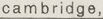
This image appears to be an architectural drawing or blueprint. It contains various plans and sections of a building or structure with detailed inscriptions, measurements, and annotations. There are both horizontal and vertical elements represented in the drawing, indicating floor plans and elevational details or section cuts. The drawings show detailed dimensions, construction notes, and material specifications. In the lower right corner, there is a stamp or label that may provide information about the architect, architectural firm, or project, but the resolution and distance of the text in that section make it challenging to read the specifics. If this is a work by a specific architect or firm, the label might indicate their names or the title of the project.
Created by gpt-4o-2024-05-13 on 2025-03-07
This image is a technical architectural drawing, showcasing detailed structural plans and section views. The document includes multiple dimensions, material specifications, and precise construction details. Key elements visible in the drawing include: - Detailed measurements and dimensions (in feet and inches), annotated along various parts of the structure. - Notations for building materials, such as "Metal Grating," "Plywood Cover," "Spruce Wood," etc. - Section and plan views indicating how different parts of the structure fit together. - Specific structural components, such as beams, flooring levels, and framing, are labeled clearly. - Handwritten notes with specifications and instructions for construction. The bottom right corner contains a title block providing information about the project, including: - The project name/location: "New York Lumber Trade Association, DuBridge & Bromberg, Inc." - The scale (1/4"= 1') and drawing number (36). - Revision details, mentioning "Walter Gropius & Marcel Breuer, Associated Architects." Overall, the drawing reflects precise engineering and architectural planning, typical of professional building design documentation.
Anthropic Claude
Created by claude-3-haiku-20240307 on 2024-12-31
This image appears to be an architectural blueprint or technical drawing. It contains various measurements, dimensions, and annotations indicating it is a detailed plan or schematic. The drawing includes several views and cross-sections, likely depicting a structural or mechanical design. There are no human faces or figures visible in this image.
Created by claude-3-opus-20240229 on 2024-12-31
The image shows an architectural blueprint or plan drawing. It contains various views and cross-sections of what appears to be a large industrial or commercial structure. The drawing includes floor plans, elevations, and detailed dimensions. Technical notes and specifications are provided in the lower right corner of the blueprint. The drawing is done in a precise, technical drafting style on aged or yellowed paper, giving it a vintage appearance.
Created by claude-3-5-sonnet-20241022 on 2024-12-31
This is an architectural drawing or blueprint that appears to be a detailed plan and section view of some architectural elements. The drawing includes technical specifications and measurements, with various cross-sections and details shown. The title block in the bottom right corner indicates this is from the architectural firm of Walter Gropius & Marcel Breuer. The drawing contains technical details for what appears to be a glazing or window system, with precise measurements and annotations. There are multiple views including a plan view and several detail sections. The drawing is done in a professional architectural drafting style typical of mid-20th century architectural documentation.
Meta Llama
Created by us.meta.llama3-2-11b-instruct-v1:0 on 2025-03-13
The image presents a detailed architectural plan, showcasing the layout of a building or structure. The plan is drawn on a large sheet of paper, with the majority of the space dedicated to the design. The drawing is rendered in pencil and features various symbols, lines, and notations that provide insight into the building's dimensions, materials, and other essential details. **Key Features:** * **Title:** The title of the plan is not visible, but it appears to be a professional architectural drawing. * **Scale:** The scale of the drawing is not explicitly stated, but it seems to be a 1:100 or 1:200 scale. * **Materials:** The plan includes notations about the materials used in the construction of the building, such as wood, steel, and concrete. * **Dimensions:** The drawing includes measurements and dimensions for various elements of the building, including walls, windows, doors, and rooms. * **Symbols:** The plan employs a range of symbols and abbreviations to convey information about the building's design and construction. These symbols may represent different types of materials, architectural features, or construction techniques. * **Notations:** The plan includes handwritten notations and annotations that provide additional context and information about the building's design and construction. * **Date:** The date of the plan is not visible, but it appears to be an older drawing, possibly from the mid-20th century. * **Architects:** The plan is attributed to Walter Gropius and Marcel Breuer, two renowned architects who were associated with the Bauhaus school. **Summary:** The image presents a detailed architectural plan that showcases the design and construction of a building. The plan includes notations about materials, dimensions, and symbols that provide insight into the building's design and construction. The plan is attributed to Walter Gropius and Marcel Breuer, two influential architects of the 20th century. Overall, the image provides a fascinating glimpse into the world of architectural design and construction.
Created by us.meta.llama3-2-90b-instruct-v1:0 on 2025-03-13
This image depicts a blueprint for a building, showcasing the floor plan and various architectural details. The blueprint is divided into sections, each representing a different area of the building, with labels and measurements providing clarity on the design. The blueprint features a mix of handwritten notes and printed text, indicating that it was created using a combination of traditional drafting techniques and modern printing methods. The use of blue ink on a white background gives the blueprint a classic appearance, reminiscent of traditional architectural drawings. In the bottom-right corner, a small box contains information about the architects who created the blueprint, including their names and contact details. This suggests that the blueprint was produced by a professional architectural firm, and the inclusion of this information adds an air of authenticity to the document. Overall, this image provides a detailed and informative look at the design of a building, offering insights into the architectural style and construction methods used in its creation.
Amazon Nova
Created by amazon.nova-lite-v1:0 on 2025-02-26
The image is a technical architectural drawing, likely a floor plan or section of a building designed by Walter Gropius and Marcel Breuer. The drawing is on a white background with black lines and annotations. The text is handwritten, and the drawing includes dimensions and notes in the margins. The drawing is labeled "Walter Gropius & Marcel Breuer" in the bottom right corner, indicating the architects who designed the building. The drawing appears to be a detailed technical plan, with measurements and annotations indicating the layout and design of the building.
Created by amazon.nova-pro-v1:0 on 2025-02-26
The image shows a white architectural blueprint with black text and lines. The blueprint contains several sections, including a plan, elevations, and details. The plan section shows a floor layout with dimensions, while the elevations section displays the building's exterior walls and windows. The details section provides specific information about the building's construction, such as the type of materials used and the size of the windows. The blueprint also includes a legend that explains the symbols and abbreviations used throughout the document.
Text analysis
Amazon