Machine Generated Data
Tags
Color Analysis
Categories
Imagga
| text visuals | 100% | |
Captions
Microsoft
created on 2018-03-22
| a close up of text on a white background | 80.2% | |
| a close up of text on a black background | 75.4% | |
| a close up of text on a white surface | 75.3% | |
OpenAI GPT
Created by gpt-4 on 2025-03-09
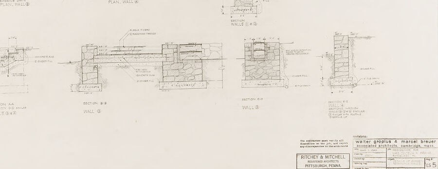
This image appears to be an architectural drawing or a set of construction documents showcasing various plans and section details for a building or structure. The drawings are technical in nature, employing standard architectural annotation, symbology, and dimensioning. In particular, the following details can be observed:
There are several plan views, which are top-down diagrams detailing the layout of walls, stairs, and other features. These plans often include annotations such as dimensions and notes explaining materials or construction methods.
Detailed cross-sections are also depicted, which are vertical "slices" through the building to show the internal structure, elevations, and details such as insulation, flooring, and wall construction.
The drawing style suggests technical precision with clean, straight lines, and the text areas contain explanations or specifications related to the construction.
There are notes and labels describing the materials (like concrete, metal, or stone) and how various building elements should be assembled.
Overall, these documents serve as instructions and guidelines for constructing the building as designed, communicating exact details necessary for builders to follow. They are an essential part of the architectural design and construction process.
Created by gpt-4o-2024-05-13 on 2025-03-09
The image is a detailed architectural drawing that features plans, elevations, and sections of masonry walls. It is part of a structural design, possibly for a historical or significant building project, as indicated by the detailed brick and stone wall sections and stair abutments.
Here is a more detailed description:
Plans:
- The top portion includes plan views labeled as "Stair Abutments Basement Plan Wall Q" and "Stair Abutments Plan Wall G." These depict the layout of walls at various building levels, with detailed dimensions and annotations regarding materials and construction specifics.
Sections:
- The bottom portion of the drawing includes several cross-sectional views. These are labeled as "Section A-A", "Section B-B", "Section C-C", depicting underlying construction details, including stone and concrete materiality, and structural reinforcement for walls G and Q.
Details:
- Masonry details illustrate how stones are to be laid and the integration of concrete and other structural supports like backing bricks or possible rebar placements.
Annotations and Notes:
- There are specific instructions and measurements given in the annotations for the construction team. These ensure that the design's integrity and specifications are upheld during the building process.
Project Information:
- Provided in the lower right corner, the drawing gives credits to the architecture firm responsible: "Ritchey & Mitchell" based in Pittsburgh, Pennsylvania, in association with "walter gropius & marcel breuer" from Cambridge, Massachusetts. This information is contained within a title block, which also includes the project number, sheet number (5), and possibly the date and scale of the drawing.
This comprehensive setup ensures that builders can accurately translate the architect's vision into physical form, maintaining structural integrity and aesthetic design intentions.
Anthropic Claude
Created by claude-3-haiku-20240307 on 2024-12-31
This image appears to be a set of architectural drawings or plans. It includes several detailed sketches, diagrams, and technical specifications related to the construction or design of a building or structure. The drawings depict various views, elevations, and cross-sections, with annotations and measurements provided. The overall layout and technical nature of the content suggest this is a professional engineering or architectural document, likely intended for use in a construction or design project.
Created by claude-3-opus-20240229 on 2024-12-31
The image shows various detailed architectural drawings and plans for what appears to be a stone or masonry wall. The drawings include front, side and section views of the wall, showing the layering and arrangement of the stonework. Dimensions and materials are labeled on the plans.
At the bottom, there is a title block indicating these are drawings for a "Water Avenue & Market Street" project, likely in Pittsburgh, PA based on the architect's office location also listed. The client seems to be "Ritchey & Mitchell", presumably the property owners or developers.
Overall, it is a set of precise, hand-drafted architectural plans typical of building and construction documentation, rendered in pencil or ink on paper or vellum. The detailed stonework implies a carefully designed, substantial masonry wall, perhaps for a commercial or public building.
Created by claude-3-5-sonnet-20241022 on 2024-12-31
This image appears to be an architectural drawing or blueprint showing various wall plans and sections. The drawing includes both plan views (shown from above) and cross-sectional views of what appears to be stone or masonry walls. There are multiple detailed sections labeled A-A, B-B, C-C, and more, showing different elevations and construction details. The plans include measurements and notations typical of architectural drawings. The document appears to be associated with architectural firm Walter Gropius & Marcel Breuer and is related to a project for Ritchey & Mitchell in Pittsburgh, Pennsylvania. The drawing is rendered in a technical style with fine lines and precise measurements, typical of professional architectural documentation.
Meta Llama
Created by us.meta.llama3-2-11b-instruct-v1:0 on 2025-03-16
The image presents a detailed architectural plan for a building, showcasing the layout and design of various rooms and spaces. The plan is divided into several sections, each highlighting different aspects of the building's design.
- Plan
- The plan is drawn to scale, with measurements and labels indicating the dimensions of each room and space.
- The plan includes a key or legend that explains the symbols and abbreviations used throughout the drawing.
- The plan is likely created using a computer-aided design (CAD) program or traditional drafting techniques.
- Sectional Views
- The sectional views provide a detailed look at the building's structure and layout from different angles.
- Each sectional view is labeled with a letter or number, corresponding to a specific location on the plan.
- The sectional views show the relationships between different rooms and spaces, as well as the building's foundation and roof.
- Elevations
- The elevations show the exterior of the building from different angles, including the front, side, and rear.
- Each elevation is labeled with a letter or number, corresponding to a specific location on the plan.
- The elevations provide a detailed look at the building's exterior design, including windows, doors, and architectural features.
- Floor Plans
- The floor plans show the layout of each floor, including the location of rooms, corridors, and stairways.
- Each floor plan is labeled with a letter or number, corresponding to a specific location on the plan.
- The floor plans provide a detailed look at the building's interior design, including the relationships between different rooms and spaces.
- Details
- The details show the design of specific architectural features, such as doors, windows, and stairways.
- Each detail is labeled with a letter or number, corresponding to a specific location on the plan.
- The details provide a detailed look at the building's design, including the materials and construction techniques used.
In summary, the image presents a comprehensive architectural plan for a building, including a plan, sectional views, elevations, floor plans, and details. The plan is drawn to scale and includes a key or legend that explains the symbols and abbreviations used throughout the drawing. The sectional views, elevations, floor plans, and details provide a detailed look at the building's design, including the relationships between different rooms and spaces, as well as the building's foundation and roof.
Created by us.meta.llama3-2-90b-instruct-v1:0 on 2025-03-16
The image presents a technical drawing of a building's floor plan and wall sections, likely created by an architect or designer. The drawing is rendered in black ink on a white background, with various symbols, labels, and annotations throughout.
Key Features:
- Floor Plan: The top-left corner of the image features a floor plan, which appears to be a multi-level structure with several rooms and corridors. The plan is drawn to scale, with measurements and dimensions labeled throughout.
- Wall Sections: Below the floor plan are several wall sections, which provide detailed views of the building's walls and their components. These sections show the construction materials, window and door locations, and other architectural features.
- Labels and Annotations: Throughout the drawing, there are numerous labels and annotations that provide additional information about the building's design and construction. These include notes on materials, dimensions, and other technical details.
- Scale and Measurements: The drawing includes a scale bar and measurements, which allow the viewer to understand the size and proportions of the building.
- Architectural Style: The drawing suggests a modernist or contemporary architectural style, with clean lines, minimal ornamentation, and an emphasis on functionality.
Overall Impression:
The image presents a detailed and technical representation of a building's design and construction. The drawing is likely intended for use by architects, engineers, contractors, and other professionals involved in the building process. The level of detail and precision suggests that the drawing is a working document, rather than a conceptual or artistic representation of the building.
Amazon Nova
Created by amazon.nova-lite-v1:0 on 2025-02-28
This image is a technical drawing or blueprint, likely from an architectural or engineering project. It contains multiple sections and plans related to a building or structure. The drawing is composed of various lines, shapes, and annotations that provide detailed information about the design and construction of the project.
The image is divided into several parts, each representing a different aspect of the project. The top left section shows a plan view of the building, indicating the layout and positioning of rooms, walls, and other structural elements. The top right section appears to be a cross-section or elevation view, showing the vertical dimensions and details of the structure.
The middle section contains multiple plans and sections, likely related to specific areas or components of the building. These include plans for stairs, abutments, and walls, as well as sections through various parts of the structure.
The bottom section includes annotations and labels that provide additional information about the project. It mentions the names of the architects, Walter Gropius and Marcel Breuer, who were associated with the Bauhaus movement and known for their modernist designs.
The drawing also includes technical specifications, measurements, and notes that would be essential for the construction and execution of the project. These details ensure that the building is constructed according to the intended design and specifications.
Overall, this image represents a comprehensive and detailed technical drawing or blueprint for a building or structure, providing architects, engineers, and construction professionals with the necessary information to bring the design to life.
Created by amazon.nova-pro-v1:0 on 2025-02-28
The image is a technical drawing of a building's architectural plan. It is a blueprint with various sections and elevations of the structure. The drawing includes details of the building's layout, including walls, windows, and doors. There are also annotations and measurements provided for specific dimensions and materials. The drawing is likely used for construction or renovation purposes, as it provides a detailed plan for the building's design and layout.
Text analysis
Amazon