Machine Generated Data
Tags
Color Analysis
Feature analysis
Amazon
| Document | 77.1% | |
Categories
Imagga
| text visuals | 100% | |
Captions
Microsoft
created on 2018-03-23
| a close up of text on a white surface | 69.9% | |
| a screenshot of text | 69.8% | |
| a screenshot of a computer | 62.3% | |
OpenAI GPT
Created by gpt-4 on 2025-03-09
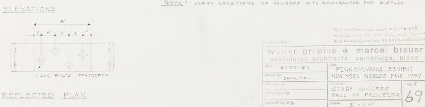
The image shows a technical drawing or architectural plan that includes details for constructing part of a structure. At the top of the drawing, there is an elevation view which provides a side perspective of the design, showing the heights and construction elements such as bolts and supports. Below the elevation is a reflected plan view, which indicates how the construction elements are laid out when looking from above, as if reflected on a horizontal plane that cuts through the structure. The drawing includes various measurements, specifications, and notes that would be important for someone constructing the item, such as bolt sizes, spacing, and materials. For example, one can see notes like "CUT OUT HERE FOR TWO HAND HANGERS," "3/8" DIA. BOLTS STAGGERED," and "4'-6" FROM STEEL STRAP." There are annotations and text blocks offering information about the project and the drawing itself, like who drew the plans, the project's affiliation, and revisions. This particular plan is associated with Walter Gropius & Marcel Breuer, associated architects from Cambridge, Massachusetts. It was drafted for the Pennsylvania Exhibit at the New York World's Fair in 1937. On the right side of the drawing, there is a stamped or printed note that includes revision dates and other administrative details. It appears to be sheet number 69 of a larger set of plans, and this specific sheet is focused on "STEEL HANGERS HALL OF PROGRESS."
Created by gpt-4o-2024-05-13 on 2025-03-09
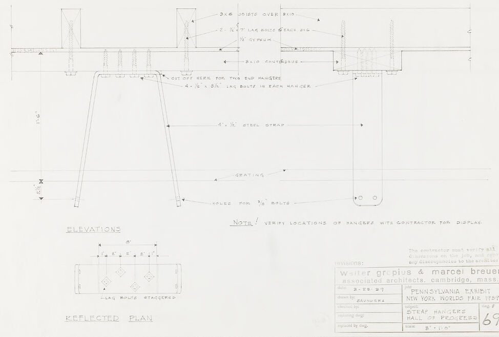
This image is a technical drawing created by the architectural partnership of Walter Gropius and Marcel Breuer. The drawing appears to be a detailed plan for the installation of steel hangers for a display, specifically for the Pennsylvania Exhibit at the New York World's Fair in 1939. The drawing includes two primary views: 1. **Elevation View** - The top part of the drawing, which shows a side view of the installation. It includes: - The positioning and details of 3 x 6 joists over some form of a grid or structure. - Instructions for cutting and installing various components like steel straps and hanger bolts. - Layers of gypsum, radio continuous material, and other structural elements. - Clear indication of dimensions and placements for lag bolts and other hardware. 2. **Reflected Plan View** - The bottom part of the drawing, which looks at the setup from below, showing: - The staggered placement of lag bolts. - The positioning that complements the elevation view. Additional notations provide: - Precise measurements. - Detailed instructions about the location of hangers and hardware specifics. - A note to verify the locations of hangers with the contractor for display accuracy. The bottom right corner contains administrative details: - Date: 8-28-39 - Job: Pennsylvania Exhibit, New York World's Fair 1939 - Detail: Steel Hangers for Hall of Progress - Drawn by: Sanderc - Approved by: Owlg (possibly initials or abbreviations of names) - It also mentions that the drawing is three feet and ten inches in scale. Overall, the drawing is a meticulous guide for the construction and installation of structural components for an exhibit, ensuring precise and accurate assembly.
Anthropic Claude
Created by claude-3-haiku-20240307 on 2024-12-31
The image appears to be an engineering drawing or schematic diagram. It contains various measurements, notes, and technical details related to the design of a structure or mechanism. The main components shown include a platform or stage, support structures, and various other elements. The drawing includes detailed dimensions, material specifications, and instructions for construction. Overall, this appears to be an architectural or engineering design document, without any identifiable human individuals present.
Created by claude-3-5-sonnet-20241022 on 2024-12-31
This is an architectural drawing/technical diagram showing strap hangers for what appears to be part of the Pennsylvania Exhibit at the 1939 New York World's Fair. The drawing includes both elevation and reflected plan views, with detailed specifications for bolt locations, steel strap dimensions, and mounting details. The architects listed are Walter Gropius & Marcel Breuer from Cambridge, Massachusetts. The drawing is dated 2-28-39 and includes scale measurements and technical notes, including one to "verify locations of hangers with contractor for display." The drawing shows precise measurements for lag bolts, continuous supports, and steel straps, typical of professional architectural documentation from that era.
Meta Llama
Created by us.meta.llama3-2-11b-instruct-v1:0 on 2025-03-16
The image presents a detailed technical drawing of a strap hanger, accompanied by a note and a table of revisions. The drawing is rendered in black ink on white paper, with the title "REFLECTED PLAN" situated at the bottom left corner. **Drawing Details:** * The drawing depicts a strap hanger from a reflected plan perspective, showcasing its design and components. * The hanger features two end hangers, each with a 4 1/2" lag bolt, and a 3x6 joist over fix. * The drawing also includes notes and annotations that provide additional information about the design and construction of the strap hanger. **Note:** * The note at the bottom of the page reads, "VERIFY LOCATIONS OF HANGERS WITH CONTRACTOR FOR DISPLAY." * This note suggests that the contractor should verify the locations of the hangers with the display contractor to ensure accurate installation. **Table of Revisions:** * The table of revisions is located in the bottom right corner of the page. * It lists the revisions made to the drawing, including the date, revision number, and description of the changes. * The table provides a clear and concise record of the revisions made to the drawing. **Overall:** * The image presents a detailed and technical drawing of a strap hanger, accompanied by a note and a table of revisions. * The drawing provides a clear understanding of the design and components of the strap hanger, while the note and table of revisions offer additional context and information about the project.
Created by us.meta.llama3-2-90b-instruct-v1:0 on 2025-03-16
The image depicts a technical drawing of a structure, likely a hanger or bracket, with detailed measurements and annotations. The drawing is rendered in black ink on white paper, featuring a central section with a rectangular shape and two legs extending downward. The top portion of the drawing includes additional components, such as a horizontal bar and vertical supports. The drawing is accompanied by various notes and labels, including "ELEVATIONS" and "REFLECTED PLAN," which suggest that the image is part of a larger set of architectural or engineering plans. The presence of a "NOTE" section at the bottom of the page indicates that the drawing may be intended for use in a specific context or application. Overall, the image appears to be a detailed and precise representation of a structural component, likely used in the design or construction of a building or other infrastructure project.
Amazon Nova
Created by amazon.nova-lite-v1:0 on 2025-02-28
The image appears to be an architectural drawing or blueprint for a steel structure, likely a display or exhibit. The drawing contains various details and specifications for the construction of the structure. Key elements of the drawing include: - A reflected plan view of the structure, showing the layout and dimensions of the steel frame and components. - Dimensions and measurements for various parts of the structure, such as the steel columns, beams, and hangers. - Notes and instructions for the contractor, such as verifying the locations of the hangers and bolts with the architect. - Details about the materials to be used, such as steel bolts, straps, and gypsum. - A list of the architects and contractors involved in the project, including Walter Gropius and Marcel Breuer, who were associated with the Harvard Graduate School of Design. The drawing provides a detailed blueprint for the construction of the steel structure, outlining the various components, materials, and specifications required for the project. It serves as a guide for the contractor to accurately build the structure according to the architect's design.
Created by amazon.nova-pro-v1:0 on 2025-02-28
The image is a technical drawing of a steel structure, likely a bridge or a similar construction. The drawing includes various annotations and measurements, indicating the design specifications and dimensions of the structure. The structure appears to be composed of steel beams and supports, with a series of vertical and horizontal elements. The drawing includes details such as the placement of bolts, the size of the steel components, and the overall layout of the structure. The purpose of this drawing is likely to provide precise instructions for the construction or fabrication of the steel structure, ensuring that the final product meets the required design specifications.
Text analysis
Amazon