
Machine Generated Data
Tags
Color Analysis
Feature analysis
Amazon
| Document | 58.4% | |
Categories
Imagga
| text visuals | 99.9% | |
| paintings art | 0.1% | |
Captions
Microsoft
created on 2018-03-23
| a close up of text on a white background | 68.4% | |
| a close up of text on a black background | 62.9% | |
| a close up of text on a white surface | 62.8% | |
OpenAI GPT
Created by gpt-4 on 2025-03-05
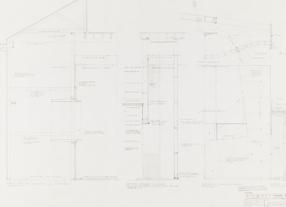
This image contains a set of architectural drawings or plans. There are several different types of views and sections of a structure detailed throughout the sheet: 1. To the left, there is a cross-section view of part of a building, showing the structure in profile from the side. This view includes annotations for various elements such as "2'-6" AIRSPACE ABOVE" and "EXISTING WALL." 2. In the top center and top right of the image, there are detail drawings of specific architectural components, possibly a railing or edge of a structure, shown in elevation and plan view, as indicated by annotations like "ANCHOR BOLT" and measurements. 3. The large drawing in the bottom center appears to be the main floor plan or a portion of it, with various rooms or areas demarcated by lines and measurements like "7'-6 1/2"" for specific distances. 4. Some detailed views for particular construction details are indicated, with scales like "SCALE 3"=1'-0"" suggesting these are close-ups for construction reference. 5. In the bottom right corner, there is a title or legend box that provides further details about the project, including scale, drawing number, and probably the name of the architect or firm responsible for the design. However, the text is too small to read clearly in this image. 6. The paper background has a slight grid structure, typical of architectural drawing paper to help with scale and proportion. The drawing style and notation indicate that this is a professional architectural plan, likely used for the construction or renovation of a building.
Created by gpt-4o-2024-05-13 on 2025-03-05
The image is a detailed architectural blueprint. It contains technical drawings and annotations that describe various sections and elevations of a wall assembly. On the left side of the blueprint, there is a "Typical Section of Display Wall Panel and Supports," which shows a vertical section including details of the wall's construction, layer by layer. Various parts such as the exterior and interior walls, roof, floor, and support beams are labeled with precise measurements and notations. In the middle, there is a detailed section drawing of the connection from the wall panel to the structure, providing a closer look at the beam and roof interface. The right section shows a plan view and elevation views indicating the arrangement of panels and other structural components. There are notes on the arrangement, measurements, and specific construction details. At the bottom right corner of the blueprint, there is a title block. It includes typical architectural details such as project title, the names of the architect or architectural firm (in this case, "Winter Griplas & Marcel Breuer"), the project location ("Assorted Exhibits, Abington, Mass"), drawing number ("A-65"), and other administrative information. The scale used for the drawings is also mentioned.
Anthropic Claude
Created by claude-3-haiku-20240307 on 2024-12-29
This image appears to be an architectural drawing or blueprint. It contains detailed technical diagrams and measurements for various structures or buildings. The drawing depicts multiple views, including elevations, plans, and sections, providing comprehensive information about the design and construction of the depicted structures. While the image does not contain any human faces, it showcases the technical expertise and precision required in architectural design and planning.
Created by claude-3-opus-20240229 on 2024-12-29
The image shows an architectural floor plan sketch. It contains various rooms and spaces labeled with their dimensions and purposes, such as "Dining room", "Kitchen", "Living room", etc. The plan includes details like doors, windows, built-in furniture, and plumbing fixtures. Measurements are provided to specify room sizes and wall lengths. The sketch has a title block in the bottom right corner with project information, but the details are too small to read clearly in this image. Overall, it appears to depict the layout design for a residential space like a house or apartment.
Created by claude-3-5-sonnet-20241022 on 2024-12-29
This image appears to be an architectural drawing or blueprint showing various technical sections and elevations of a building. The drawing includes multiple cross-sectional views that detail the interior spaces and structural elements. It's rendered in a typical architectural style with thin black lines on a white background, showing dimensions, levels, and construction details. The drawing appears to be labeled and includes multiple views from different angles, which is standard practice in architectural documentation. There are notations and measurements throughout the drawing, and it appears to be a professional technical document, likely used for construction or renovation purposes.
Meta Llama
Created by us.meta.llama3-2-11b-instruct-v1:0 on 2025-03-11
The image presents a detailed architectural blueprint, showcasing the floor plan and elevation of a building. The blueprint is rendered in black and white, with various lines, symbols, and text used to convey the design and specifications of the structure. **Key Features:** * **Floor Plan:** The floor plan is depicted on the left side of the image, featuring a rectangular shape with a gable roof. The plan includes several rooms, corridors, and staircases, as well as labels and measurements to indicate the dimensions and layout of the space. * **Elevation:** The elevation is shown on the right side of the image, providing a detailed view of the building's exterior. The elevation includes information about the building's height, width, and depth, as well as the location of windows, doors, and other architectural features. * **Text and Symbols:** Throughout the blueprint, various text and symbols are used to convey important information about the building's design and construction. These may include notes on materials, dimensions, and other technical specifications. * **Scale:** The blueprint includes a scale at the bottom, which allows the viewer to understand the relationship between the drawing and the actual building. The scale is likely expressed in units such as feet or meters. * **Legend:** A legend is provided at the bottom of the blueprint, explaining the meaning of various symbols and abbreviations used throughout the drawing. This helps the viewer to interpret the information presented in the blueprint. **Overall:** The blueprint provides a comprehensive and detailed representation of the building's design and layout. It is likely intended for use by architects, engineers, or contractors who need to understand the building's specifications and construction requirements. The use of text, symbols, and scales allows for a clear and concise communication of the building's design and construction details.
Created by us.meta.llama3-2-90b-instruct-v1:0 on 2025-03-11
The image presents a detailed architectural drawing of a building's floor plan, showcasing various rooms and spaces. The drawing is rendered in black ink on white paper, with precise measurements and labels indicating the different areas. **Key Features:** * **Floor Plan:** The central focus of the image, the floor plan displays a range of rooms, including a theater, dressing rooms, and other ancillary spaces. * **Measurements:** The drawing includes precise measurements, allowing for accurate scaling and construction. * **Labels:** Each room and space is labeled, providing clear identification and functionality. * **Architectural Details:** The drawing incorporates architectural details such as doors, windows, and structural elements, offering a comprehensive understanding of the building's design. **Conclusion:** The image provides a thorough and detailed representation of the building's floor plan, showcasing the architect's vision and attention to detail. The inclusion of measurements, labels, and architectural details ensures that the drawing serves as a valuable resource for construction and planning purposes.
Amazon Nova
Created by amazon.nova-lite-v1:0 on 2025-01-10
The image appears to be an architectural drawing or blueprint for a building project. The drawing contains various sections and details of the building's design, including: - A floor plan showing the layout of the rooms and spaces within the building. - Elevations or views of the building's exterior, likely showing the front, side, and rear elevations. - Sections or cross-sections of the building, providing a vertical view of the structure's internal layout and materials. - Details of specific components or features, such as doors, windows, and finishes. The drawing is labeled with various measurements, dimensions, and notes, indicating the intended scale and specific design elements. The drawing also includes the names of the architects or designers, Walter Gropius and Marcel Breuer, as well as the project name, "Theatrical Entrance Details." Overall, the image represents a detailed and comprehensive architectural design for a building project, likely created by professional architects or designers to guide the construction process.
Created by amazon.nova-pro-v1:0 on 2025-01-10
The image shows a detailed architectural plan for a building. The plan is divided into several sections, each providing specific information about the structure. The top left section shows the floor plan, with dimensions and annotations indicating the layout of rooms and spaces. The top right section displays a cross-sectional view of the building, revealing the interior structure and floor levels. The bottom left section provides a detailed elevation of the building's exterior, showcasing the facade and architectural features. The bottom right section includes additional details, such as window sizes, door locations, and other construction specifications. The overall plan appears to be a comprehensive blueprint for the construction of a multi-story building, with meticulous attention to detail and precise measurements.
Text analysis


