Machine Generated Data
Tags
Color Analysis
Categories
Imagga
| text visuals | 99.2% | |
| paintings art | 0.6% | |
| food drinks | 0.1% | |
Captions
Microsoft
created on 2018-03-22
| a close up of text on a white surface | 65.8% | |
| a close up of text on a white background | 64% | |
| close up of text on a white surface | 61% | |
OpenAI GPT
Created by gpt-4 on 2025-03-09
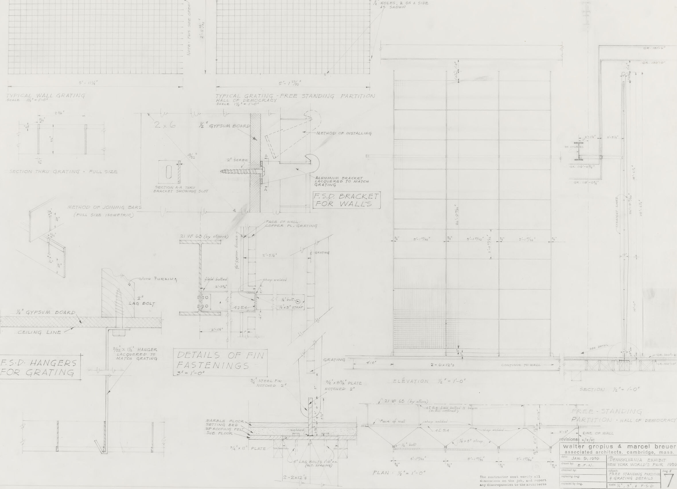
This image appears to be a technical drawing or architectural plan. The plan includes a variety of detailed diagrams and sections depicting different aspects of building components. There are annotations and measurements indicating the dimensions and materials to be used. The plans seem to focus on grating installations and include details such as: - Typical wall grating - Typical grating 'free standing' - Method of joining bars - F.S.D. brackets for walls - Details of fin fastenings - Elevations, sections, and plans for free-standing partitions - Annotations regarding materials such as gypsum board and steel plates The lower right corner contains additional information which includes the names Walter Gropius & Marcel Breuer, suggesting a connection to these notable architects. It also mentions The Architectural Forum, January 1942, indicating that this plan may have been published or related to a project at that time. There is also an approval stamp with a date, possibly when the drawing was reviewed or submitted. Keep in mind that the image might contain additional fine details which are not legible in this review, and there might be more context within the broader set of documents or plans from which this image was taken.
Created by gpt-4o-2024-05-13 on 2025-03-09
The image depicts a detailed architectural drawing for a free-standing partition, particularly focusing on grating installation. The drawing appears to be from the office of architects Walter Gropius and Marcel Breuer, associated with the Hall of Democracy project. Key elements include: 1. **Grating Details**: A typical wall grating is shown with dimensions, along with full-size sections and isometric views to display how the grating integrates with the structure. Notations include dimensions and materials, like the ¾ inch gypsum board. 2. **Elevation and Plan Views**: Elevation (vertical view) and plan (horizontal view) of the partition are provided to show the layout and spacing of the grating. 3. **Joining Methods**: Diagrams illustrate the method of joining grating sections and the hardware used (e.g., F.S.S. (Freely Spanning Space) brackets and hangers). 4. **Fastening Details**: The specifics of how the fins are fastened, including the use of anchor bolts and washers. 5. **Dimensions and Materials**: A detailed breakdown of all relevant measurements and materials required for execution is present. 6. **Annotations**: Notes clarify specific instructions, such as ensuring all screws are countersunk and other installation tips. This drawing is technical and highly detailed, intended for use by construction professionals for accurate assembly of the free-standing partition system.
Anthropic Claude
Created by claude-3-haiku-20240307 on 2024-12-31
The image appears to be an engineering or architectural drawing, containing various technical details and specifications. The drawing includes detailed plans, schematics, and dimensions for a wall-mounted grating system, including the dimensions and placement of supporting brackets. There are also various technical annotations and labels throughout the drawing, providing additional information about the construction and installation of the grating system.
Created by claude-3-opus-20240229 on 2024-12-31
The image shows a detailed architectural drawing or blueprint. It depicts plans and elevations for what appears to be a building or structure labeled "R.S.P. Hangers for Grating". The drawing includes various measurements, dimensions, labels, and annotations providing technical specifications for the construction or installation of these hangers and associated gratings. The blueprint style with white lines and text on a gray background is typical of architectural and engineering drawings used to convey detailed plans to builders and contractors.
Created by claude-3-5-sonnet-20241022 on 2024-12-31
This image appears to be an architectural or engineering technical drawing showing various detailed specifications and diagrams. The drawing includes multiple views and sections detailing what appears to be grating installations and mounting brackets. There are several components labeled including "F.S.D. HANGERS FOR GRATING" and "F.S.D. BRACKET FOR WALLS" with precise measurements and installation details. The drawing contains grid patterns at the top, various elevation views, and detailed cross-sections showing how different components fit together. The drawing is done in a professional drafting style with dimensions, notes, and technical specifications clearly marked. The document appears to be created by an architectural firm and includes a title block in the lower right corner with project information.
Meta Llama
Created by us.meta.llama3-2-11b-instruct-v1:0 on 2025-03-16
The image depicts a technical drawing, likely for a building or architectural project. It is a detailed, hand-drawn plan with various sections and labels, including: * **Grids**: The drawing features multiple grids, which are used to measure and scale the design. * **Labels**: There are several labels throughout the drawing, including "WALL GRATING", "F.S.D. BRACKET FOR WALLS", "F.S.D. HANGERS FOR GRATING", and "DETAILS OF FIN FASTENINGS". * **Dimensions**: The drawing includes various dimensions, such as measurements for walls, doors, and windows. * **Symbols**: There are several symbols used throughout the drawing, including arrows, lines, and shapes. * **Text**: The drawing includes text, including notes and instructions for the construction of the building. Overall, the image appears to be a technical drawing for a building or architectural project, likely created by an architect or engineer. It provides a detailed plan for the construction of the building, including measurements, labels, and symbols.
Created by us.meta.llama3-2-90b-instruct-v1:0 on 2025-03-16
The image presents a detailed architectural drawing, likely created for a construction project. The drawing is rendered in pencil on a white background and features various elements, including: * A grid pattern at the top, which may represent a wall or ceiling. * A series of lines and shapes that appear to be a floor plan or elevation. * Several notes and labels throughout the drawing, including "F.S.D. HANGERS FOR GRATING" and "DETAILS OF FIN FASTENINGS." * A signature or title block in the bottom-right corner, which reads "Walter Gropius & Marcel Breuer Associates Architects Cambridge Mass." Overall, the image suggests that it is a technical drawing intended for use in the design and construction of a building or structure. The level of detail and the use of technical terminology suggest that it was created by a professional architect or engineer.
Amazon Nova
Created by amazon.nova-lite-v1:0 on 2025-02-28
The image is a technical drawing sheet that appears to be an architectural or construction blueprint. The drawing contains various sections and details related to the installation of a free-standing partition wall system. The drawing includes multiple sections, each labeled with different titles such as "TYPICAL STANDING PARTITION", "METHOD OF JOINING BARS", "DETAILS OF FIN FASTENINGS", and "F.S.D. HANGERS FOR GRATING". The drawing features several diagrams and annotations that provide information on the dimensions, materials, and installation techniques for the partition system. There are also tables and grids that contain measurements and specifications related to the various components of the system. The drawing appears to be created using a technical drafting tool, likely a CAD (Computer-Aided Design) software, as the lines and annotations are precise and well-organized. The drawing sheet is white, and the annotations and diagrams are in black, making it easy to read and understand the technical details. Overall, the image represents a technical drawing that provides detailed instructions and specifications for the installation of a free-standing partition wall system, likely used in commercial or industrial settings.
Created by amazon.nova-pro-v1:0 on 2025-02-28
The image appears to be a technical drawing or blueprint of a construction project. It features various sections and annotations related to the construction process. The drawing includes details such as the dimensions of different components, the layout of the structure, and specific instructions for the construction team. The image is in black and white, and the text and lines are clearly visible, indicating that it is a well-organized and detailed plan for the project.
Text analysis
Amazon