Machine Generated Data
Tags
Color Analysis
Categories
Imagga
| text visuals | 100% | |
Captions
Microsoft
created on 2018-03-22
| a close up of text on a white surface | 82.6% | |
| a screenshot of a computer | 76.3% | |
| a close up of a computer screen with text | 70.6% | |
OpenAI GPT
Created by gpt-4 on 2025-03-09
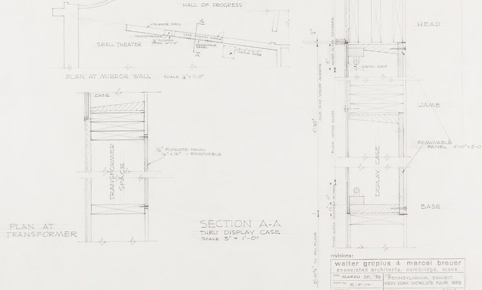
This image depicts a set of technical drawings or architectural plans. The drawings include various sections and plans for what appears to be an exhibit space, with references to components such as a "Hall of Progress," a "Small Theater," and "Mirror Wall." The plans are detailed and include scales, measurements, and annotations suggesting the drawings are for precise construction or assembly purposes. The views consists of section view and plan views showcasing specific parts of the design. In the bottom right-hand corner, there are credits and revisions to the plans, listing "Walter Gropius & Marcel Breuer associated architects, Cambridge, Mass." There is a date "March 26, 1939," indicating the time of the plans, and it is noted that these are for the "PENNSYLVANIA EXHIBIT NEW YORK WORLD'S FAIR 1939". At the bottom, there's a stamp or sign-off that reads "E.F.N." and hand-written notes include additional measurements and the word "DISPLAY CASE." The drawings appear to be drafted by hand, characteristic of architectural plans prior to the wide usage of computer-aided design (CAD) software. The drawing is technical and would be used by builders or architects who are creating or studying the space detailed here.
Created by gpt-4o-2024-05-13 on 2025-03-09
The image is an architectural drawing for a display case in the Hall of Progress. The detailed drawing includes multiple views and sections, suggesting a comprehensive design approach. Here's a breakdown of the components in the image: 1. **Plan at Mirror Wall:** - It shows the layout of the mirror wall and its relation to the Hall of Progress and the Small Theater. - Scale is given as 3/4" = 1' - 0". 2. **Plan at Transformer:** - This section highlights the transformer space within the display case. - It includes notes about the 1/4" plywood panel being removable. 3. **Section A-A:** - A cross-sectional view through the display case. - It details the structure from the head to the base, including metal strips, jamb, and the removable panels. - Scale of 3/4" = 1' - 0". 4. **Additional Specifics:** - The drawing is dated March 26, 1939. - Associated architects are Walter Gropius and Marcel Breuer, based in Cambridge, Massachusetts. - The project is for the Pennsylvania Exhibit at the New York World's Fair 1939. - Revision notes and instructions for the contractor to verify dimensions on-site before starting any work. The drawing is rich in technical details, highlighting materials to be used and specific measurements, ensuring precision in the construction of the display case.
Anthropic Claude
Created by claude-3-haiku-20240307 on 2024-12-31
The image appears to be an architectural drawing or plan for a structure called the "Hall of Progress". It contains detailed plans and sections for what looks like a display or exhibition case, with dimensions and labels for various components like the "base", "jamb", "panel", and "head". The drawing also includes a floor plan view at the top showing the layout of the "Small Theater" and other spaces within the "Hall of Progress". Overall, this seems to be a technical design document related to the construction or fabrication of some type of exhibit or display within a larger building or venue.
Created by claude-3-5-sonnet-20241022 on 2024-12-31
This is an architectural drawing/blueprint showing various technical details for a display case installation in the Hall of Progress at the 1939 New York World's Fair. The drawing includes multiple views: 1. A plan view at the mirror wall showing the layout of a small theater area 2. A plan view of a transformer case 3. A section A-A view through the display case 4. Detailed measurements and specifications for various components The drawing was created by Walter Gropius & Marcel Breuer Associated Architects from Cambridge, Massachusetts, dated March 26, '39 for the Pennsylvania Exhibit. The drawing includes specifications for removable panels, plywood panels, and various structural elements like the jamb, head, and base of the display case. The scale notations indicate different scales used for different views (1"=1'-0" and 3"=1'-0"). This appears to be drawing number 72 in what was likely a larger set of architectural plans. The drawing is executed in a professional architectural drafting style typical of the period, with clean lines and precise measurements marked throughout.
Meta Llama
Created by us.meta.llama3-2-11b-instruct-v1:0 on 2025-03-16
The image presents a detailed architectural drawing for a display case, showcasing the design and specifications of the case. The drawing is divided into sections, each highlighting a specific aspect of the case's construction. * **Section A-A Thru Display Case** * This section provides a detailed view of the display case from a side perspective, illustrating its dimensions and features. * The drawing includes measurements and labels for various components, such as the base, jambs, and head. * The section also highlights the location of the removable panel, which allows for easy access to the interior of the case. * **Plan at Mirror Wall** * This section shows the plan view of the display case, with measurements and labels indicating the placement of the case within the larger architectural context. * The drawing includes details about the surrounding walls, including the location of the mirror wall and the placement of the display case. * **Plan at Transformer** * This section provides a detailed view of the transformer space, highlighting its dimensions and features. * The drawing includes measurements and labels for various components, such as the transformer, electrical connections, and ventilation systems. * **Revisions** * The revisions section lists changes made to the original design, including updates to the dimensions, materials, and features of the display case. * The section also includes notes and comments from the architects and engineers involved in the project. Overall, the image provides a comprehensive overview of the display case's design and construction, highlighting its key features and specifications. The detailed drawings and measurements allow for a clear understanding of the case's dimensions, materials, and features, making it an essential tool for architects, engineers, and builders working on the project.
Created by us.meta.llama3-2-90b-instruct-v1:0 on 2025-03-16
This image depicts a technical drawing of an exhibit display case, likely for the 1939 New York World's Fair. The drawing is divided into two main sections: a floor plan and a section view. **Floor Plan:** * The floor plan shows the layout of the exhibit, including the location of the display case, a small theater, and a hall of progress. * The plan is labeled with various details, such as the scale (1/4" = 1'-0") and the location of mirrors and transformers. * The plan also includes notes on the construction of the display case, including the use of removable panels and the installation of a plywood panel. **Section View:** * The section view shows a detailed cross-section of the display case, including the base, jambs, and removable panels. * The section view is labeled with various details, such as the scale (3" = 1'-0") and the location of metal strips and glass. * The section view also includes notes on the construction of the display case, including the use of removable panels and the installation of a plywood panel. **Additional Information:** * The drawing includes additional information, such as the name of the architect (Walter Gropius & Marcel Breuer) and the date of the drawing (March 28, 1939). * The drawing also includes a note indicating that the revisions were made by E.F.N. and that the drawing was approved by the architect. Overall, this technical drawing provides a detailed and accurate representation of the exhibit display case, including its layout, construction, and materials. It is likely that this drawing was used to guide the construction of the exhibit and to ensure that it met the desired specifications and standards.
Amazon Nova
Created by amazon.nova-lite-v1:0 on 2025-02-28
The image is a technical architectural drawing of a display case for the "Hall of Progress" at the Pennsylvania World's Fair in 1939. The drawing consists of two sections: a plan view at the mirror wall and a section view labeled "A-A" through the display case. The plan view shows the layout of the display case, including dimensions and annotations like "TRANSFORMER" and "MIRROR WALL." The section view provides a detailed cross-sectional view of the display case, showing its internal structure, materials, and dimensions. The drawing is labeled with the architect's name, Walter Gropius & Marcel Breuer, and the date of the project, March 26, 1939. The drawing also includes a scale of 1/4" = 1'-0" for the plan view and 3'-0" = 1'-0" for the section view.
Created by amazon.nova-pro-v1:0 on 2025-02-28
The image is a technical drawing of a section of a building, specifically detailing the structural elements and layout of a section labeled "A-A" through the display case. The drawing includes various components and dimensions, with annotations and labels for clarity. The drawing is divided into two main parts. The left side depicts a section of the building's interior, showing a wall with a "mirror wall" and a "small theater" adjacent to it. Above the small theater, there is a "hall of progress," indicating a progression or sequence of spaces. The right side of the drawing shows a detailed elevation of a structure labeled "Section A-A thru Display Case." Key components and labels in the drawing include: - "Hall of Progress" at the top, suggesting a sequential or narrative space. - "Mirror Wall" adjacent to the small theater, indicating a reflective surface. - "Small Theater" labeled next to the mirror wall, suggesting a performance or viewing space. - "Plan at Mirror Wall" and "Plan at Transformer" on the left, indicating floor plans or layouts at specific points. - "Section A-A thru Display Case" on the right, detailing the elevation through a display case. - "Scale 4'-1'-0"" at the bottom, providing the scale for the drawing. - "Case" and "Transformer" labels, indicating specific elements within the section. - "Plywood Panel" and "Removable Panel" labels, detailing materials and components. - "Base" and "Head" labels, indicating the bottom and top of the section. The drawing also includes dimensions and annotations such as "3'-1'-0"" and "4'-10'-3'-0"", providing specific measurements for the components. The bottom of the drawing contains additional information, including the date "March 26, 1959," the location "Pennsylvania Exhibit New York World's Fair 1959," and the scale "4'-3'-1'-0"". The drawing is a technical representation used for construction or architectural purposes, providing detailed information about the structure and layout of the section through the display case.
Text analysis
Amazon