Machine Generated Data
Tags
Color Analysis
Feature analysis
Amazon
Clarifai

Clarifai
| Whiteboard | 47.5% | |
Categories
Imagga
created on 2018-03-22
| text visuals | 99% | |
| paintings art | 0.7% | |
| food drinks | 0.1% | |
| nature landscape | 0.1% | |
Captions
Microsoft
created by unknown on 2018-03-22
| a close up of text on a whiteboard | 78.8% | |
| a close up of a whiteboard | 76.7% | |
| close up of text on a whiteboard | 76.6% | |
Clarifai
No captions written
Salesforce
Created by general-english-image-caption-blip on 2025-05-11
a photograph of a drawing of a plan for a house
Created by general-english-image-caption-blip-2 on 2025-06-29
a drawing of a house with a floor plan
OpenAI GPT
Created by gpt-4 on 2024-12-16
This image shows an architectural drawing or blueprint. The paper is predominantly white, with lines and annotations in a thin, precise style consistent with architectural sketches. The drawing appears to represent a floor plan, indicated by defined spaces with measurements and notations for construction specifics.
In the top right corner, there's text reading "NOTE," followed by construction details. It refers to specific materials such as "1/4" cork on 2" Celotex" and mentions some finishing details like "plastic joint strips." Additional annotations concerning construction materials and methods are found around the drawing.
The drawing is detailed with various dimensions noted in feet and inches, indicative of scale and size for the rooms and walls. Gridlines intersect at right angles, creating a sense of structure and aiding in the scaling of the plan.
In the bottom right corner of the image, there are some handwritten revisions dated June 7, 1939, and the architects associated with this drawing are listed as "Walter Gropius & Marcel Breuer ASSOCIATED ARCHITECTS CAMBRIDGE, MASS." Below this text, there is more information written in a different handwriting and stamped text, possibly referring to a client or a project title (e.g., "MRS. STORROW (FORD)" and "BRATTLE LOOK TRAIL").
On the far right side, a part of an approval or revision stamp is visible, along with a portion of a date which is cut off, and a circular stamp number "8." The page also shows signs of age, with some discolored spots and a creased upper corner.
Overall, this image provides a detailed look at a piece of architectural history, showcasing the meticulous planning and design work that goes into creating a building.
Created by gpt-4o-2024-05-13 on 2024-12-16
This image shows an architectural drawing or blueprint. The drawing is detailed with measurements and annotations, indicating it likely represents a plan for a building or a specific architectural element. There are detailed notes and specifications on the right side of the drawing, and the bottom right corner contains information regarding revisions, which are dated June 12, 1956. The names of the associated architects, Walter Gropius and Marcel Breuer, along with their location in Cambridge, Massachusetts, are also included. Additionally, the drawing has a scale, and there's a section labeled "8" possibly indicating a page or section number.
Anthropic Claude
Created by claude-3-haiku-20240307 on 2024-12-16
This image appears to be an architectural plan or technical drawing. It contains various lines, measurements, and notations that suggest it is a detailed schematic or blueprint for a construction project. There are no human faces or figures visible in the image. The drawing seems to depict the layout and dimensions of some kind of structure or building, but without more context, I cannot determine the specific nature of the project.
Created by claude-3-5-sonnet-20241022 on 2024-12-16
This appears to be an architectural drawing or blueprint, specifically showing what looks like a floor plan or elevation view. The drawing is created by Walter Gropius & Marcel Breuer Associated Architects from Cambridge, Massachusetts, as indicated in the title block at the bottom right. The drawing shows various linear elements and appears to be quite minimalist in style, with clean lines and geometric forms. The layout seems to feature a central section with extending wings or segments. There are some annotations and dimensions marked on the drawing, though they're not entirely clear in this reproduction. The paper appears to be aged or yellowed slightly, particularly visible in one corner. The drawing is labeled with the number "8" and includes revision dates, showing this was likely part of a larger set of architectural plans.
Created by us.anthropic.claude-3-5-sonnet-20241022-v2:0 on 2025-06-26
This is an architectural drawing or blueprint showing a floor plan detail. The drawing appears to be from the office of Walter Gropius & Marcel Breuer, Associated Architects in Cambridge, Massachusetts. It's a technical drawing showing what appears to be a deck or porch detail with various measurements and construction notes. The drawing is primarily in pencil on white paper and includes dimension lines, structural elements, and annotations. There's a drawing number "8" in the bottom right corner, along with revision dates and other technical information in the title block. The drawing style is characteristic of mid-20th century architectural documentation, with clean lines and precise detailing.
Meta Llama
Created by us.meta.llama3-2-11b-instruct-v1:0 on 2024-12-16
The image presents a technical drawing of a building's floor plan, accompanied by detailed notes and specifications. The drawing is rendered in black ink on white paper, with the title "revisions: JUNE 12-20 SECTIONAL" inscribed in the bottom-right corner.
Key Features:
- Floor Plan: The floor plan is drawn in black ink, showcasing the layout of the building's interior spaces.
- Notes and Specifications: Various notes and specifications are scattered throughout the drawing, providing additional information about the building's design and construction.
- Title: The title "revisions: JUNE 12-20 SECTIONAL" is written in the bottom-right corner, indicating the date of the revisions.
- Architects' Information: The names of the architects, Walter Gropius and Marcel Breuer, are listed in the bottom-right corner, along with their associated firm, "Walter Gropius & Marcel Breuer associated architects. cambridge, mass."
- Date: The date "JUNE 12-20" is inscribed in the bottom-right corner, indicating when the revisions were made.
- Sectional Drawing: The drawing is labeled as a sectional drawing, suggesting that it is a detailed representation of the building's interior spaces.
Overall Impression:
The image presents a detailed and technical drawing of a building's floor plan, complete with notes and specifications. The inclusion of the architects' names and the date of the revisions adds context to the drawing, suggesting that it is a professional and well-documented design.
Created by us.meta.llama3-2-90b-instruct-v1:0 on 2024-12-16
The image depicts a technical drawing of a building's floor plan, likely created by an architect. The drawing is rendered in black ink on white paper and features various symbols, labels, and measurements that provide detailed information about the building's layout and design.
Key Features:
- Floor Plan: The central element of the image is the floor plan, which shows the arrangement of rooms, corridors, and other spaces within the building.
- Symbols and Labels: The drawing includes various symbols and labels that indicate different features such as doors, windows, walls, and staircases.
- Measurements: The drawing includes measurements in feet and inches, which provide precise information about the size and scale of the building.
- Architectural Details: The drawing also includes architectural details such as column locations, beam spans, and roof pitches.
- Revision Notes: The bottom-right corner of the image contains revision notes, which indicate changes made to the original design.
- Stamp: The bottom-right corner also features a stamp with the name "Walter Gropius & Marcel Breuer" and the location "Cambridge, Mass." This suggests that the architects responsible for the design were Walter Gropius and Marcel Breuer, who were both prominent figures in modernist architecture.
Overall Impression:
The image presents a detailed and technical representation of a building's floor plan, showcasing the expertise and attention to detail of the architects involved. The use of symbols, labels, and measurements provides a clear understanding of the building's layout and design, while the revision notes and stamp offer insight into the design process and the architects' involvement.
Amazon Nova
Created by amazon.nova-lite-v1:0 on 2025-02-25
This image is a technical drawing of a floor plan. The floor plan is labeled as "First Floor Plan" and includes details such as room dimensions, wall locations, and notes. The drawing is in black and white and is on a white background. The floor plan is divided into sections, with each section labeled with a letter and a number. The drawing also includes a legend that explains the symbols used in the plan. The floor plan appears to be for a residential or commercial building, with various rooms and spaces marked out.
Created by amazon.nova-pro-v1:0 on 2025-02-25
The image shows a blueprint of a building. The blueprint is a technical drawing that shows the layout of the building, including the dimensions, walls, and other structural elements. The blueprint is divided into different sections, each labeled with a number and a description of the section. The blueprint also includes a legend that explains the symbols and abbreviations used in the drawing. The blueprint is a detailed plan that architects and engineers use to design and construct buildings.
Google Gemini
Created by gemini-2.0-flash on 2025-05-13
Here's a description of the image based on the provided information:
The image is a scan of an architectural drawing, likely a blueprint, on a light-colored (possibly off-white) paper. The drawing is done in a fine line style, probably in pencil or a similar drafting medium.
Content of the Drawing:
- Floor Plan: The primary focus is a floor plan or a segment of one. It shows a rectangular structure with several vertical lines across the interior, potentially indicating joists or framing.
- Stair Detail: There is a detail of a staircase or stairway landing.
- Section Detail: A section detail labelled "Section A-A" which depicts a cross-sectional view of a wall or structural element, showing the layers and components.
- Labels and Dimensions: Throughout the drawing, there are annotations with dimensions, material specifications, and other relevant construction notes.
Textual Elements:
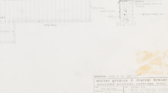
- Title Block: The bottom portion of the image contains a title block with information like the project name ("MRS. STORROW [FORD], Lincoln, Mass"), the architects ("Walter Gropius & Marcel Breuer, associated architects, Cambridge, Mass."), the date ("May 24, 1949"), the drawing subject ("First Floor Framing"), the scale ("1/4"=1'-0"), and a sheet number ("8").
- Revisions: A revision date is present ("JUNE 12, 1930 SECTION").
- General Note: A note at the bottom of the image contains information.
- Specific Note: A note is also located toward the upper-right
Overall Impression:
The image is a technical drawing that communicates precise information about the construction or design of a building. The aging and faintness of some of the lines and text suggest it is an original document. There appear to be some stains or spots on the paper, particularly near the title block.
Created by gemini-2.0-flash-lite on 2025-05-13
This image is an architectural blueprint, likely a top-down plan view of a building. The drawing uses pencil or a similar medium on a light-colored paper.
Key Features:
- Plan View: The primary focus is on the horizontal layout of the building, with walls, roof elements, and structural components.
- Sections & Details: There's a clear indication of a section labeled "Section A-A" with a closer look at a wall's construction layers, including framing, siding, and other details.
- Annotations: The drawing is filled with annotations including dimensions, material specifications (e.g., "2x4 studs," "3x4 Western White Pine"), and construction notes.
- Structural Elements: The plan details roof joists, sill plates, and possibly the location of doors, windows, and staircases.
- Title Block: A title block at the bottom right identifies the architects as Walter Gropius & Marcel Breuer, their location in Cambridge, Mass. and the project as the "Mrs. Storrow Ford" residence, specifying the view as a "First Floor Framing" detail with a scale of 1/4" = 1'-0". The date of the revision is June 12, 35.
- Revisions: The annotation "revisions" indicates that this version of the blueprint was updated.
- Notes: The drawing has a note specifying "Staging in all steel beams to attach wood railing strip."
The overall impression is a technical document intended for the construction of a building, with the plan view being the core of the drawing, and detailing materials and assembly of building elements.
Mistral Pixtral
Created by us.mistral.pixtral-large-2502-v1:0 on 2025-05-30
The image depicts an architectural floor plan drawing. It appears to be a detailed blueprint of a building's layout, likely a residential or small commercial structure. Here are the key features and details:
Layout and Rooms:
- The plan shows various rooms, including what seems to be a living room, kitchen, bathroom, and bedrooms.
- There are clear demarcations for walls, doors, and windows.
- The layout includes dimensions for the different spaces, which are marked in feet and inches.
Annotations:
- The drawing includes several notes and annotations, such as "Ceiling," "Wall," and "Floor," indicating specific structural elements.
- There are labels for different areas and features within the building, like "Kitchen," "Bath," and "Bedroom."
Revisions:
- A note at the bottom left indicates revisions were made in June 1954.
- The revision note specifies that the contractor must verify all dimensions on the job and report any discrepancies.
Architect Information:
- The architects are listed as Walter Gropius and Marcel Breuer, associated architects from Cambridge, Massachusetts.
- The drawing is dated May 20, 1954.
- The project title is "Mr. & Mrs. George Nelson, New York, N.Y."
- The drawing number is 2216, and the sheet number is 8.
Scale and Drawing Details:
- The scale of the drawing is noted as 1/4" = 1'-0".
- The plan includes a title block in the bottom right corner with the architects' names and the project details.
This floor plan provides a comprehensive overview of the building's layout, including room dimensions, structural elements, and specific notes for construction.
Qwen
No captions written
Text analysis
Amazon