Machine Generated Data
Tags
Color Analysis
Feature analysis
Amazon
Clarifai

Clarifai
| Whiteboard | 91.8% | |
Categories
Imagga
created on 2018-03-22
| text visuals | 100% | |
Captions
Microsoft
created by unknown on 2018-03-22
| a close up of text on a whiteboard | 70% | |
| a close up of a whiteboard | 68.2% | |
| close up of text on a whiteboard | 66.7% | |
Clarifai
No captions written
Salesforce
Created by general-english-image-caption-blip on 2025-05-11
a photograph of a drawing of a plan for a kitchen
Created by general-english-image-caption-blip-2 on 2025-06-28
architectural drawings of a building with a door and window
OpenAI GPT
Created by gpt-4 on 2025-03-07
The image shows a technical architectural drawing with various views of a structure. The drawing includes multiple sections such as plan views, side elevations, and cross-sections. Annotations and measurements accompany each sketch, providing details on dimensions and construction notes. The plans appear to be hand-drawn, a common practice before the widespread use of computer-aided design (CAD) software.
In the bottom right corner, there is a title block containing information. It includes the word "revisions" followed by names, presumably of the architects or designers involved in the project, which read "Walter Gropius & Marcel Breuer" and an address in Cambridge, Massachusetts. There are fields for the date, client, job, checked by, project, and drawn by, though this information is not legible in the image. The title block helps identify the project, track revisions, and maintain a record of the creation and modification of the drawing.
The style and detail suggest that this drawing is part of a professional architectural project, possibly dating back to a time when such blueprints were manually created. Walter Gropius and Marcel Breuer are notable figures in modernist architecture, known for their work in the Bauhaus movement.
Created by gpt-4o-2024-05-13 on 2025-03-07
This image is a detailed architectural drawing that includes multiple views and sections of a structure. The drawing appears to be technical with precise measurements and notes. It includes a plan view, a side elevation, and various section views labeled accordingly. The label in the bottom right corner indicates that the drawing is associated with Walter Gropius and Marcel Breuer, distinguished architects based in Cambridge, Massachusetts. It also specifies that the drawing is related to an entrance detail, with additional revisions noted. The drawing is meticulously annotated, with different parts labeled for clarity and exact dimensions provided.
Anthropic Claude
Created by us.anthropic.claude-3-5-sonnet-20241022-v2:0 on 2025-06-25
This image appears to be an architectural drawing or blueprint showing multiple views of what seems to be an entrance or structural element. The drawing includes:
- A plan view (labeled "PLAN")
- A section view (labeled "SECTION A-A'")
- A side elevation view
- Another section view
The drawings are technical in nature, showing various dimensions and construction details with thin lines and annotations. The drawing appears to be from an architectural firm, as indicated by text in the title block in the bottom right corner. The drawings show both vertical and horizontal elements, possibly for some kind of entrance structure or partition, with what appears to be vertical slats or posts shown in the elevation view.
The drawing is rendered in a light, pencil-like style typical of architectural drawings, with different line weights used to show different elements and depths. There are various measurements and notes scattered throughout the drawing, though they're not clearly legible in this image.
Created by claude-3-haiku-20240307 on 2024-12-31
This image appears to be an architectural or engineering drawing or blueprint. It contains various technical diagrams, measurements, and labels, indicating it is likely a detailed design or plan for some kind of structure or construction project. The drawing includes a side elevation, a section view, and what seems to be a title or legend at the bottom. While the image does not depict any human figures, it showcases the technical and precise nature of the architectural or engineering design process.
Created by claude-3-opus-20240229 on 2024-12-31
This image shows architectural plans and elevations for a structure labeled as "Side Elevation" and "Section A-A". The plans include detailed dimensions and measurements for various components of the structure, such as the roof line, columns/posts, and window openings. The plans are hand-drawn in pencil on grid paper and include some handwritten notes and revisions. In the lower right, a title block provides information about the project, including the architects "Walter Gropius & Marcel Breuer", location "Cambridge, Mass.", and date "July, 17,1938".
Created by claude-3-5-sonnet-20241022 on 2024-12-31
This is an architectural drawing or blueprint showing various views of what appears to be an entrance design. The drawing includes multiple technical views:
- A plan view (top left)
- A section A-A' (middle)
- Another section view (bottom left)
- A side elevation (bottom right)
The drawings are done in pencil on gridded paper and include various measurements and annotations. The drawing shows structural details including posts, panels, and what appears to be some sort of grating or vertical slat design in the side elevation view.
The bottom of the drawing includes a title block with architectural firm information and drawing details. The drawing appears to be sheet number 50 and includes space for revisions. The level of detail suggests this is a professional architectural drawing, likely for construction purposes.
Meta Llama
Created by us.meta.llama3-2-11b-instruct-v1:0 on 2025-03-13
The image depicts a technical drawing of a building's elevation, featuring multiple sections and details. The drawing is divided into several sections, each labeled with its corresponding section number. The sections include:
- Section A-A: This section appears to be a cross-section of the building, showing the interior layout and structure.
- Section B-B: This section is likely a longitudinal section, providing a view of the building's length and width.
- Section C-C: This section may be a transverse section, offering a view of the building's width and depth.
The drawing also includes various details such as door and window openings, staircases, and other architectural features. The use of different line weights and symbols suggests that the drawing is intended to convey specific information about the building's design and construction.
In the bottom-right corner of the image, there is a table with text that appears to be a list of revisions made to the drawing. The table includes columns for the revision number, date, and description of the change.
Overall, the image provides a detailed and technical representation of the building's elevation, highlighting its various components and features.
Created by us.meta.llama3-2-90b-instruct-v1:0 on 2025-03-13
The image presents a technical drawing, likely an architectural plan or blueprint, featuring various sections and elevations of a building or structure. The drawing is rendered in black ink on white paper, with handwritten notes and labels throughout.
Key Features:
- Section A-A: A detailed section view of the building, showcasing its internal layout and structural elements.
- Elevation: A side view of the building, highlighting its exterior features and dimensions.
- Plan: A top-down view of the building, providing an overview of its floor plan and room layout.
- Notes and Labels: Handwritten notes and labels are scattered throughout the drawing, offering additional information about the building's design and construction.
Revisions:
- Walter Gropius & Marcel Breuer: The names of the architects responsible for the design are listed in the bottom-right corner of the drawing.
- Associated Architects, Cambridge, Mass.: The location of the architectural firm is also noted.
- Date: The date of the drawing is not explicitly stated, but it appears to be from the mid-20th century based on the style and content.
- Scale: The scale of the drawing is not indicated, but it appears to be a standard architectural scale.
Conclusion:
The image presents a detailed technical drawing of a building or structure, showcasing its various sections and elevations. The drawing is likely an architectural plan or blueprint, created by Walter Gropius and Marcel Breuer in the mid-20th century. The inclusion of handwritten notes and labels adds to the drawing's technical nature, providing additional information about the building's design and construction.
Amazon Nova
Created by amazon.nova-lite-v1:0 on 2025-02-26
The image appears to be a set of architectural drawings or plans for a building or structure. The drawings contain various sections, elevations, and details that provide information about the design and construction of the project. Here are some key observations:
The drawings contain multiple sections and elevations, indicating that the project involves a complex structure with different components and views.
The drawings are labeled with various details, such as dimensions, materials, and construction notes. For example, there are notes about "full size" and "one-half full size" drawings, indicating that the plans are intended for both detailed design and general layout purposes.
The drawings contain revisions and updates, as indicated by the "revisions" section at the bottom of the image. This suggests that the project is in the design or construction phase, and changes are being made to the original plans.
The drawings are attributed to "walter gropius & marcel breuer," which are the names of two prominent architects known for their work in the modernist style. This suggests that the project is likely a modernist building or structure.
The drawings contain various symbols and annotations, such as arrows, lines, and labels, which provide additional information about the design and construction of the project.
Overall, the image appears to be a set of architectural drawings for a modernist building or structure designed by Walter Gropius and Marcel Breuer. The drawings contain various sections, elevations, and details that provide information about the design and construction of the project, and they include revisions and updates to reflect changes made during the design or construction phase.
Created by amazon.nova-pro-v1:0 on 2025-02-26
The image is a detailed architectural drawing of a building, divided into several sections. The top section is labeled "Section A-A" and features a cross-sectional view of the building, showing the structure's interior layout, including walls, floors, and ceiling heights. The bottom section is labeled "Side Elevation" and shows the exterior of the building from the side, highlighting the building's height, windows, and door placement. The drawing includes precise measurements and annotations, indicating the scale and dimensions of the building. The drawing also includes a legend with various symbols and notes, providing additional information about the building's construction and design.
Google Gemini
Created by gemini-2.0-flash on 2025-05-13
Here is a description of the image.
The image is an architectural drawing consisting of several views of a structure or building element. The drawing is done in pencil on what appears to be vellum or similar drafting paper.
In the upper left is a "PLAN," depicting a horizontal layout of what seems to be the interior space, including what appear to be shelves. The dimensions are noted with lines and measurements. To the right of the plan is a partial view of the facade, showing the structural components and detailing the overhang or canopy.
Below the plan, on the left, is a "SECTION" drawing, showing a vertical cut through the structure, revealing the interior and construction details. To the right of the section is a "SIDE ELEVATION," which shows the building or structure from the side, with multiple vertical supports and a horizontal element.
On the right side of the drawing is a "SECTION A-A" which is labeled as "ONE-HALF FULL SIZE". This shows a detailed cross-section of a roof or overhang, with notes on the materials and construction methods.
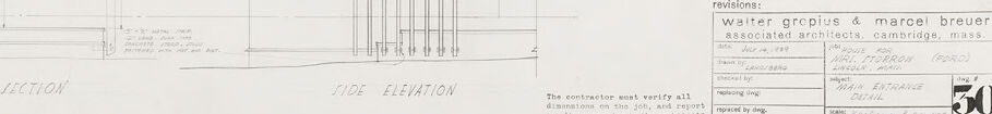
At the bottom right of the drawing is the title block, labeled "revisions" and filled with architectural information. The drawing is identified as being by Walter Gropius & Marcel Breuer, associated architects from Cambridge, Massachusetts. The project is for a "HOUSE FOR MIKE STORROW (FORD)" and the subject is "MAIN ENTRANCE DETAIL". The drawing number is "50".
The bottom left corner includes a note stating, "The contractor must verify all dimensions on the job, and report any discrepancies to the architects."
Created by gemini-2.0-flash-lite on 2025-05-13
This is an architectural drawing, a blueprint, likely for the construction of a building or a part of it. It appears to be a plan for the "Main Entrance Detail" of a house for "Morrow (Ford)," designed by Walter Gropius and Marcel Breuer, associated architects in Cambridge, Massachusetts.
Here are the key features and details visible:
- Layout: The drawing contains several views, including a "Plan," a "Section A-A" (cross-section), and a "Side Elevation." The different views give information about different dimensions and angles.
- Annotations and Labels: The drawing is heavily annotated with text, measurements, and labels indicating the materials, dimensions, and construction details.
- Scale: The scale of the drawing is mentioned (e.g., "one-half full size" for the section and "5/16" = 1' 0" for the plan), which is critical for contractors and builders to understand the dimensions properly.
- Materials and Structure: It shows the structure and materials to be used, such as "siding," "roofing" (with specific types like "Ruiberoid" mentioned), and details about joists, studs, and other structural components.
- Revisions Block: The lower right corner includes a "revisions" block, indicating the architects involved, the name and location of the project (the house for Morrow in Lincoln, presumably), and details about the revision process.
- Construction Notes: There is also a statement for the contractor to verify dimensions and report any discrepancies.
- Drafting Style: The drawing is done in a technical drafting style, typical of architectural blueprints. It uses lines, dimensions, and symbols to represent the design.
In summary, the image is a technical drawing providing a detailed guide for constructing a part of a building, providing all of the necessary data for someone to build it.
Mistral Pixtral
Created by us.mistral.pixtral-large-2502-v1:0 on 2025-05-31
The image is an architectural drawing, specifically a detailed section and elevation drawing for a building. Here's a breakdown of the components:
Sections:
- Section A-A: This section view appears to show a cross-section of the building, detailing the internal structure. It includes various layers and components, such as walls, floors, and roofing elements.
- Section B: This section view provides another cross-sectional perspective, likely at a different part of the building or from a different angle. It includes details of the structural elements and possibly some mechanical or electrical components.
Elevations:
- Side Elevation: This view shows the side of the building, detailing the external facade. It includes elements like windows, walls, and possibly some structural supports.
Annotations:
- The drawing includes various annotations and notes, which provide additional information about the materials, dimensions, and specific details of the construction.
- There is a note indicating that the contractor must verify all dimensions and that the architect is not responsible for any discrepancies.
Revisions:
- The drawing includes a revision history, noting changes made by Walter Gropius and Marcel Breuer, associated architects from Cambridge, Massachusetts.
- The revisions include dates and specific changes made to the drawings.
Drawing Number:
- The drawing is labeled with the number "50" in the bottom right corner, indicating its place in a series of drawings.
Overall, the image provides a detailed technical representation of a building's structure, including both internal and external views, along with important notes and revisions for construction purposes.
Qwen
Created by Qwen/Qwen2.5-VL-7B-Instruct on 2025-07-21
This is a technical architectural drawing, likely representing a detailed plan or section of a building or structural component. The drawing includes multiple views and annotations:
Plan View: Located in the top-left corner, this view shows the layout of the structure's interior from above. It includes dimensions, notations, and details of the layout such as the placement of beams, columns, and other structural elements.
Section View A-A': This view, positioned in the upper right, provides a cross-sectional view along the indicated line A-A'. It shows the depth and structure of the walls, beams, and other structural components, including notes on materials, dimensions, and construction details.
Side Elevation: Located in the lower center, this view shows the side of the structure from one angle, detailing the height and alignment of the beams, columns, and the overall structure's profile.
Annotations and Dimensions: Throughout the drawing, there are various annotations, dimensions, and notes that provide specific instructions and measurements for the construction of the structure.
Revision Information: In the bottom-right corner, there is a revision record that includes the name of the architectural firm (Walter Gropius & Marcel Breuer, Associated Architects), the project title, date, and any changes or revisions made to the drawing.
The drawing is labeled as a "Main Entrance Detail," and it appears to be part of a larger set of architectural plans. The style and precision of the drawing suggest it is from a professional architectural firm and is intended for detailed construction purposes.
Created by Qwen/Qwen2.5-VL-72B-Instruct on 2025-07-21
This image is an architectural drawing created by Walter Gropius and Marcel Breuer, who were associated architects based in Cambridge, Massachusetts. The drawing is labeled as "MAIN ENTRANCE DETAIL" and is part of a larger project, indicated by the reference number 30. The date on the drawing is June 16, 1938, and it was checked by someone with the initials "JCS."
The drawing includes several views of the main entrance detail:
- Plan: This shows a top-down view of the entrance, detailing the layout and arrangement of the components.
- Section A-A: This section view provides a vertical cross-section of the entrance, showing the internal structure and layers of materials used.
- Section: Another section view is included, offering a different vertical perspective of the entrance.
- Side Elevation: This shows the side view of the entrance, detailing the external appearance and dimensions.
The drawing includes various notes and annotations, likely providing instructions for construction and detailing specific dimensions and materials. The scale of the drawing is noted as 3/4" = 1'-0", indicating that the drawing is not full size but a scaled-down version for easier handling and clarity.
Text analysis
Amazon