Machine Generated Data
Tags
Color Analysis
Feature analysis
Amazon
Clarifai

AWS Rekognition
| Document | 88.3% | |

Categories
Imagga
created on 2018-03-22
| text visuals | 100% | |
Captions
Microsoft
created by unknown on 2018-03-22
| a close up of text on a whiteboard | 77% | |
| close up of text on a whiteboard | 74.5% | |
| a close up of a whiteboard | 73.2% | |
Clarifai
No captions written
Salesforce
Created by general-english-image-caption-blip on 2025-05-11
a photograph of a drawing of a plan for a house
Created by general-english-image-caption-blip-2 on 2025-06-28
a drawing of a building with a plan and a diagram
OpenAI GPT
Created by gpt-4 on 2025-03-07
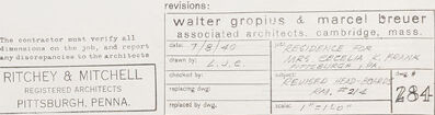
This image depicts an architectural drawing or blueprint. The drawing includes a front elevation, a plan view, and an end elevation of what is labeled as "REVISED HEAD-BOARDS RM. #214." It appears to be a design for a room's headboard feature, suggesting that it might be part of an interior design or renovation project.
The drawing is quite detailed, with various dimensions and annotations indicating specific design elements and sizes. Written notes and lines pointing to different parts of the design provide further information about materials, finishes, and construction details.
In the lower right corner, there's a title block with additional information. It lists revisions and contains signatures or initials, likely indicating approval by the responsible parties. Notable names mentioned in the revision block are "Walter Gropius & Marcel Breuer, associated architects, Cambridge, Mass." They are well-known figures in the field of architecture.
The drawing is produced by "Ritchey & Mitchell Registered Architects, Pittsburgh, Penna." which gives us a clue about the architectural firm or individuals responsible for this work.
On the bottom and left margins, there are indications of a scale (not visible in the image), which is typical for architectural drawings to convey the precise relationships between the depicted elements and their real-life sizes.
Created by gpt-4o-2024-05-13 on 2025-03-07
This image displays a technical architectural drawing for revised headboards in Room #214. It shows two primary views: the front elevation (at a scale of 1/2" = 1'-0") and the end elevation (at a scale of 1" = 1'-0").
The front elevation details the dimensions, materials, and construction notes for a headboard, specifying elements like dimensions (both overall and specific sections), materials such as 3/4" maple faced plywood, and locations for screws. The end elevation provides a side view that complements the details given in the front elevation.
Various notes and construction instructions are included on the drawing. Labeling information, such as architectural firm names (Walter Gropius & Marcel Breuer, Associated Architects, Cambridge, Mass) and registered architects (Ritchey & Mitchell, Pittsburgh, Penna), is provided at the bottom right corner of the drawing. There are also references to revisions, with dates and revision numbers (for instance, revisions on 7/31/52 and 12/3/52) as well as the initials of drafting personnel. The plan seems to be meticulously detailed for precise construction specifications.
Anthropic Claude
Created by us.anthropic.claude-3-5-sonnet-20241022-v2:0 on 2025-06-24
This image appears to be an architectural drawing or blueprint showing front elevations and headboard details. The drawing is labeled as "REVISED HEAD-BOARD DWG. #514" and includes architectural specifications and measurements. The document appears to be created by Walter Gropius & Marcel Breuer, associated architects from Cambridge, Mass., with additional attribution to Ritchey & Mitchell, registered architects from Pittsburgh, PA. The drawing shows technical details and measurements in what appears to be a professional architectural format, with various sections and elevations clearly marked. The drawing is primarily in black and white, with typical architectural line work and notations.
Created by claude-3-haiku-20240307 on 2024-12-31
The image appears to be an architectural plan or engineering drawing. It shows an elevation or front view of a structure, with various annotations and measurements indicating the different components and dimensions of the design. The drawing appears to have been revised, as indicated by the text "REVISED HEAD-SEAMS EN. # 214" at the bottom. Overall, the image depicts a technical, engineering-focused representation of a proposed or existing structure.
Created by claude-3-opus-20240229 on 2024-12-31
This image shows an architectural drawing or blueprint for what appears to be an overhead view of a bridge deck or platform. The drawing has dimensions and annotations indicating the length and width of different sections. There are notes at the bottom specifying materials like "Walter girphius & marcel breuer" and referring to the "revised Dead Load Plan". The schematic style and technical details suggest this is an engineering or architectural plan for a structure.
Created by claude-3-5-sonnet-20241022 on 2024-12-31
This is an architectural drawing or blueprint showing elevations for what appears to be a head-board design. The drawing is labeled "REVISED HEAD-BOARD P.M. #514" and includes both front and end elevation views. The document appears to be a technical drawing with detailed measurements and specifications. At the bottom of the page, there are architectural firm stamps and information, including references to Walter Gropius & Marcel Breuer as well as Ritchey & Mitchell from Pittsburgh, PA. The drawing is primarily in black and white with a clean, professional layout typical of architectural documentation. The head-board design shown includes various sections with detailed dimensioning and appears to be drawn to scale.
Meta Llama
Created by us.meta.llama3-2-11b-instruct-v1:0 on 2025-03-14
The image presents a technical drawing of a room's front elevation, accompanied by a list of specifications and measurements. The drawing is rendered in pencil on white paper, featuring a rectangular shape with a smaller rectangle within it. The smaller rectangle is divided into sections, each containing various symbols and numbers that likely represent different components or features of the room.
Key Features:
- Front Elevation: The drawing depicts the front elevation of a room, providing a detailed view of its exterior.
- Specifications and Measurements: A list of specifications and measurements is provided below the drawing, likely including details such as room dimensions, material requirements, and construction techniques.
- Pencil Drawing: The drawing is created using pencil on white paper, giving it a clean and professional appearance.
- Rectangular Shape: The drawing features a rectangular shape with a smaller rectangle within it, which may represent a section or area of the room.
- Symbols and Numbers: Various symbols and numbers are used throughout the drawing to represent different components or features of the room, such as doors, windows, and electrical outlets.
- Technical Drawing: The image appears to be a technical drawing, likely created for architectural or construction purposes.
Purpose:
The purpose of this image is to provide a detailed and accurate representation of a room's front elevation, along with its specifications and measurements. This information can be used by architects, builders, and other professionals to plan and construct the room according to the design.
Created by us.meta.llama3-2-90b-instruct-v1:0 on 2025-03-14
The image presents a technical drawing of a building's floor plan, accompanied by detailed notes and specifications. The drawing is rendered in black ink on white paper, with a prominent title at the bottom that reads "RITCHEY & MITCHELL REGISTERED ARCHITECTS PITTSBURGH, PENNA."
The top section of the drawing features a detailed floor plan, complete with measurements and annotations. Below this, a series of handwritten notes provide additional information about the building's design and construction. These notes include details such as the location of doors, windows, and other features, as well as specifications for materials and finishes.
In the bottom-right corner of the drawing, a small box contains the names of the architects responsible for the design, along with their contact information. This suggests that the drawing was created for professional purposes, likely as part of a larger architectural project.
Overall, the image provides a detailed and informative look at the design and construction of a building, highlighting the importance of careful planning and attention to detail in the architectural process.
Amazon Nova
Created by amazon.nova-lite-v1:0 on 2025-02-26
This image is a technical architectural drawing, likely a floor plan or section view, featuring a detailed layout of a residential building. The drawing is labeled "REVISED HEAD-BOARDS RM. #214," indicating that it is a revision of a previous design. The drawing includes various annotations and dimensions, suggesting it is intended for construction purposes. The drawing is signed by "RITCHEY & MITCHELL," indicating the architectural firm responsible for the design. The drawing also includes a reference to "WALTER GROPIUS & MARCEL BREUWER," suggesting that the design may be influenced by or related to the work of these architects. Overall, the image appears to be a professional architectural drawing intended for use in the construction of a residential building.
Created by amazon.nova-pro-v1:0 on 2025-02-26
The image shows a page from a construction blueprint, which is a technical drawing used in the planning and execution of construction projects. The blueprint includes detailed instructions and specifications for the construction of a building or structure. The blueprint is divided into sections, each with its own set of instructions and specifications. The blueprint includes a table of contents, which lists the different sections of the blueprint and their corresponding page numbers. The blueprint also includes a title block, which provides information about the project, such as the name of the architect, the date of the blueprint, and the scale of the drawing. The blueprint is a valuable tool for architects, engineers, and construction workers, as it provides a detailed plan for the construction of a building or structure.
Google Gemini
Created by gemini-2.0-flash on 2025-05-13
Here's a description of the image based on your request:
The image is an architectural drawing titled "REVISED HEAD-BOARDS RM. #214". It appears to be a design for headboards, likely for a residential space. The drawing consists of two main views: "FRONT ELEVATION" and "END ELEVATION". The front elevation shows the layout and dimensions of the headboards, indicating their placement relative to beds and cases. There are notes providing additional details about the fixtures, heating grilles, mounting methods, and other specifications. The end elevation shows a profile view of the headboard, giving an idea of its depth and shape.
Below the drawing, there are details about the architects, revisions, and other administrative information. The architects are listed as Walter Gropius & Marcel Breuer, associated architects from Cambridge, Massachusetts. The date of the drawing is 7/8/40, and the project is for a residence for Mrs. Cecelia K. Frank. The contractor is instructed to verify all dimensions on the job and report any discrepancies to the architects, Ritchey & Mitchell, who are registered architects from Pittsburgh, Pennsylvania.
Created by gemini-2.0-flash-lite on 2025-05-13
This is an architectural drawing of revised headboards for room #214. The drawing is in the style of a blueprint, with hand-drawn lines and annotations. It includes both a front elevation and an end elevation view. The headboards are shown as being attached to a wall. The drawing also includes notes and revisions. The architects of the drawing are Walter Gropius & Marcel Breuer, associated architects of Cambridge, Mass. The drawing date is 7/8/40.
Mistral Pixtral
Created by us.mistral.pixtral-large-2502-v1:0 on 2025-05-31
The image is an architectural drawing titled "Revised Head-boards KM, #214." It appears to be a detailed design plan for a headboard structure, likely for a building or monument. The drawing includes both front and end elevations, each drawn at a scale of 1/2" = 1'0".
Key Features:
Front Elevation:
- The front view shows a symmetrical design with several vertical elements, possibly columns or pillars.
- There are inscriptions and markings indicating measurements and specific details of the structure.
- The drawing includes annotations such as "Area A-A" and "Location of SEE," which likely refer to specific sections or elements within the design.
End Elevation:
- The end view provides a side perspective of the headboard structure.
- Similar to the front elevation, it includes detailed measurements and annotations.
Notes and Instructions:
- There are handwritten notes below the drawings providing additional instructions or clarifications about the design.
- These notes mention specifics about the materials and construction methods, such as the use of "3/4" plywood" and "2x4" framing.
- There are also instructions regarding the assembly and finishing of the structure, including painting and lettering details.
Revisions and Approvals:
- The drawing includes a section for revisions, indicating that Walter Gropius and Marcel Breuer, associated architects from Cambridge, Massachusetts, have reviewed the plans.
- There is a stamp from "Ritchey & Mitchell Registered Architects Pittsburgh, Penna," indicating their involvement or approval.
Scale and Measurements:
- The drawing is meticulously detailed with precise measurements, ensuring accuracy in construction.
- The scale is clearly marked, aiding in the interpretation of the dimensions provided.
Overall, the image is a comprehensive architectural plan for a headboard structure, complete with detailed elevations, notes, and approval stamps from the involved architects.
Qwen
Created by Qwen/Qwen2.5-VL-7B-Instruct on 2025-07-21
This image appears to be an architectural drawing or blueprint, specifically a perspective or elevation drawing of a room labeled "REVISED HEAD-BOARDS RM. #214." It includes detailed dimensions and annotations, indicating the placement and design of headboards or similar structural elements in the room.
The drawing includes:
- A front elevation view of the room.
- An end elevation view, which shows the side view of the room.
- Various dimensions such as "14' x 12'6" (check on job)" and "14' x 12'0"" which seem to refer to the dimensions of the room.
There is text and annotations indicating specific elements like "location of bed," "location of bed," and "location of bed," which further suggest that the drawing is focused on the arrangement and layout of beds or headboards in a bedroom.
The bottom of the image includes names and affiliations such as "Walter Gropius & Marcel Breuer," "Ritchey & Mitchell (Registered Architects Pittsburgh, Penna.)," and a date "7/15/40," which might indicate the date the drawing was created.
This blueprint seems to be part of a larger architectural project, likely related to the design and construction of a building or a specific room within a building, and it is reviewed and signed off by architects and possibly engineers.
Created by Qwen/Qwen2.5-VL-72B-Instruct on 2025-07-21
This image is an architectural drawing, specifically an elevation view of revised headboards for a room labeled "RM. #214." The drawing is detailed and includes both a front elevation and an end elevation.
- Front Elevation: This view shows the headboards with various dimensions and notes. There are detailed illustrations of the headboards, including the location of bedding and the dimensions of the headboards themselves.
- End Elevation: This view provides a side perspective of the headboard, showing its depth and how it connects to the wall.
The drawing includes various annotations and specifications, such as:
- "APPROX. 51'-6" (CHECK ON JOB)"
- "LOCATION OF BED"
- "DIMENSIONS OF CASE (SEE DRAWING #257)"
At the bottom of the drawing, there is a stamp or label indicating the architects involved:
- "Walter Gropius & Marcel Breuer"
- "Associated Architects, Cambridge, Mass."
There is also a stamp for "Ritchey & Mitchell, Registered Architects, Pittsburgh, Pa."
The drawing number "284" is indicated in the bottom right corner. The date "7/8/40" suggests the drawing was created or revised on July 8, 1940.
Text analysis
Amazon