Machine Generated Data
Tags
Color Analysis
Feature analysis
Amazon
Clarifai
AWS Rekognition
| Passport | 60.1% | |

Categories
Imagga
created on 2018-03-22
| text visuals | 97.5% | |
| paintings art | 2.4% | |
Captions
Microsoft
created by unknown on 2018-03-22
| a close up of text on a white background | 72.1% | |
| a close up of text on a black background | 66.3% | |
| a close up of text on a white surface | 66.2% | |
Clarifai
No captions written
Salesforce
Created by general-english-image-caption-blip on 2025-05-11
a photograph of a drawing of a plan for a house
Created by general-english-image-caption-blip-2 on 2025-06-28
a drawing of a building with a plan and drawings
OpenAI GPT
Created by gpt-4 on 2024-12-16
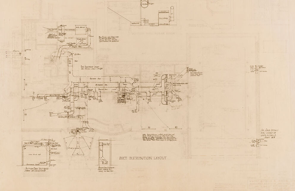
The image displays a technical engineering drawing or blueprint labeled "DUCT DISTRIBUTION LAYOUT". The drawing contains a series of interconnected lines and annotations indicating the layout of ducts within a building or set of buildings. This includes a network of straight and angular lines representing the duct paths, possibly for an HVAC (heating, ventilation, and air conditioning) system. Various sections are labeled with technical specifications, measurements, and notes relevant to the construction and installation of the ductwork. The design is intricately detailed, which is typical for construction plans, enabling builders to install systems according to precise engineering specifications. The background of the image is a light shade, with the drawing itself executed in a darker tone, providing contrast and visibility for the intricate details. This sort of layout ensures accurate construction and is essential for the functionality of the building's climate control systems.
Created by gpt-4o-2024-05-13 on 2024-12-16
The image is a technical drawing titled "Duct Distribution Layout." It appears to be a schematic diagram of a building's air duct system, showcasing how the ducts are distributed and connected. The drawing includes various labels, annotations, and arrows indicating the flow and direction of air.
There are numerous detailed diagrams and notes explaining the different parts of the duct system. Several sections of the drawing provide specific details on equipment placement, measurements, and construction details related to the air distribution system. At the bottom left, there are detailed segments labeled "Factory Zero Wetbulb" and other specific notes and annotations.
Overall, the drawing is a technical and detailed representation of the HVAC or ductwork system within a building.
Anthropic Claude
Created by claude-3-haiku-20240307 on 2024-12-16
This image appears to be a duct distribution layout, which is a detailed engineering diagram or blueprint. It shows a complex network of ducts, pipes, and various components that are likely part of an HVAC (heating, ventilation, and air conditioning) or other building system. The diagram contains numerous technical labels, measurements, and schematics that provide detailed information about the design and configuration of this duct distribution system.
Created by claude-3-5-sonnet-20241022 on 2024-12-16
This appears to be an architectural or engineering drawing showing a duct distribution layout. It's a technical schematic that details the routing and configuration of what seems to be an HVAC or ventilation system. The drawing is rendered in a sepia or brownish tone, typical of older technical drawings or blueprints. It shows various ducts, connections, and distribution paths throughout what appears to be a building or facility, with detailed measurements and annotations. The drawing includes both plan views and some detailed sections or elevations in the lower portion of the image. The lines are precise and technical in nature, showing the pathways and intersections of the ductwork system.
Created by us.anthropic.claude-3-5-sonnet-20241022-v2:0 on 2025-06-26
This image appears to be a technical engineering drawing or schematic diagram, specifically labeled as a "DUCT DISTRIBUTION LAYOUT." It shows a complex system of ducts and pathways drawn in a blueprint style with various annotations, measurements, and technical details. The drawing is done in a light or sepia tone, typical of architectural or engineering drawings, and includes multiple interconnected passages, junctions, and detailed specifications. The layout appears to be quite intricate, with various branches and connections spreading across the page in different directions. There are also some detailed section views or close-up drawings in the lower portion of the image that show specific construction details or cross-sections of the duct system.
Meta Llama
Created by us.meta.llama3-2-11b-instruct-v1:0 on 2024-12-16
The image presents a detailed duct distribution layout, showcasing a comprehensive system for air circulation and ventilation. The layout is meticulously designed to ensure efficient airflow throughout the space.
- Duct Distribution Layout
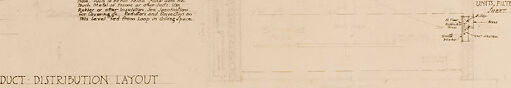
- The layout is drawn on a large sheet of paper, with the title "DUCT DISTRIBUTION LAYOUT" prominently displayed at the bottom center.
- The layout is divided into several sections, each representing a different part of the duct system.
- The sections are labeled with numbers and letters, indicating the location and function of each component.
- The layout includes various symbols and notations, such as arrows, lines, and boxes, to represent different types of ducts, vents, and other components.
- The layout also includes measurements and dimensions, providing a clear understanding of the scale and proportions of the system.
- The overall design of the layout suggests a high level of attention to detail and a focus on optimizing airflow and ventilation.
In summary, the image provides a detailed and informative representation of a duct distribution layout, highlighting the complexity and sophistication of the system. The layout is well-organized and easy to follow, making it an effective tool for understanding and analyzing the airflow and ventilation in the space.
Created by us.meta.llama3-2-90b-instruct-v1:0 on 2024-12-16
The image presents a technical drawing of a duct distribution layout, showcasing the intricate details of a ventilation system. The drawing is rendered in black ink on a beige background, with various components and labels carefully annotated.
Key Features:
- Ducts: The primary focus of the drawing is the ductwork, which is depicted in a series of interconnected lines and shapes. The ducts vary in size and shape, indicating different functions and capacities within the system.
- Labels and Annotations: Throughout the drawing, labels and annotations provide essential information about each component. These include descriptions of the ducts, valves, and other equipment, as well as measurements and specifications.
- Valves and Equipment: In addition to the ducts, the drawing also illustrates various valves and equipment that are integral to the ventilation system. These components are carefully labeled and annotated to ensure clarity and understanding.
- Background: The beige background of the drawing provides a clean and neutral backdrop for the technical details. It allows the viewer to focus on the intricate design and layout of the duct distribution system.
Overall Impression:
The image effectively conveys the complexity and sophistication of the duct distribution layout. The level of detail and annotation suggests that this drawing was created for a specific purpose, such as planning, installation, or maintenance. The use of a beige background helps to minimize visual clutter, making it easier to interpret the technical information presented.
Amazon Nova
Created by amazon.nova-pro-v1:0 on 2025-02-27
The image appears to be a technical drawing or blueprint of a duct distribution layout. The drawing is on a piece of paper that has a slightly yellowish hue, indicating that it may be an older document. The drawing depicts a complex network of ducts and pipes, with various symbols and annotations indicating different components and connections. The text "DUCT DISTRIBUTION LAYOUT" is prominently displayed at the top of the drawing, suggesting that it is a detailed plan or design for a ductwork system.
Created by amazon.nova-lite-v1:0 on 2025-02-27
The image appears to be a technical drawing or blueprint of a duct distribution layout for an industrial or commercial building. The drawing shows various components and connections of a ductwork system, including:
Main ducts: The main ducts are shown as large, thick lines running horizontally and vertically throughout the drawing. They represent the primary pathways for air distribution within the building.
Branch ducts: Smaller, thinner lines branching off the main ducts represent the branch ducts that distribute air to individual rooms or zones.
Fittings and accessories: Various symbols and annotations indicate the locations of fittings, accessories, and equipment such as diffusers, grilles, dampers, and filters.
Dimensions and labels: The drawing includes dimensions, labels, and notes to provide specific information about the ductwork layout, such as duct sizes, airflow rates, and equipment specifications.
Section views: Some parts of the drawing are shown in section views, which provide a cross-sectional view of the ductwork to illustrate internal components and connections.
The drawing is likely created using technical drafting software or traditional drafting techniques on paper. It serves as a detailed reference for engineers, contractors, and other professionals involved in the design, installation, and maintenance of the ductwork system.
Google Gemini
Created by gemini-2.0-flash on 2025-05-12
Here's a description of the image:
The image appears to be a scan of an old architectural or engineering drawing. The paper has a slightly yellowed or aged appearance.
The drawing depicts a "Duct Distribution Layout" with various details and diagrams. It includes schematics of ductwork, sections of walls with annotations, and labels for different areas or equipment. There are also notes and specifications written on the drawing in a technical style. The drawing includes labels such as "Railway Ave", "By-Passes Ave", and "Starter Ave" to indicate the layout of the ductwork. It also includes scale details for the layout of the units and fixtures. The overall impression is that of a detailed plan for a ventilation or HVAC system, likely from the mid-20th century or earlier.
Created by gemini-2.0-flash-lite on 2025-05-12
This is a technical drawing, likely a blueprint, illustrating a "Duct Distribution Layout." The drawing is detailed, featuring a network of lines representing ducts and pipes, with handwritten labels and notes scattered throughout. Various architectural and mechanical components are represented, including rooms, ventilation systems, and associated equipment. The style suggests a historical or vintage document, possibly a construction plan. The drawing is complex, requiring specialized knowledge to fully interpret.
Mistral Pixtral
Created by us.mistral.pixtral-large-2502-v1:0 on 2025-05-30
The image depicts a detailed architectural or engineering drawing, specifically a duct distribution layout. Here are the key elements and features of the drawing:
Title and Labels: The drawing is titled "Duct Distribution Layout" at the bottom center. There are various sections and components labeled throughout the drawing, such as "Exhaust Air," "Return Air," "Supply Air," "Fan," and "Duct."
Layout: The layout shows a plan view of a building or a section of a building, with various rooms and spaces identified. The ductwork is illustrated, showing how air is distributed throughout the different areas.
Ductwork: The ducts are represented by lines and shapes, indicating their paths and connections. Different types of ducts are labeled, such as supply air ducts, return air ducts, and exhaust air ducts.
Components: Various components are marked, including fans, dampers, and diffusers. These components are essential for the proper functioning of the HVAC (Heating, Ventilation, and Air Conditioning) system.
Dimensions and Measurements: The drawing includes dimensions and measurements for the ducts and other components, providing precise information for installation and construction.
Sections and Details: There are smaller inset drawings or sections that provide more detailed views of specific parts of the ductwork or components. These details help in understanding the intricate parts of the system.
Notes and Annotations: The drawing contains notes and annotations that provide additional information about the layout, components, and installation instructions.
Scale and Orientation: The drawing likely includes a scale and orientation indicator to help in interpreting the layout accurately.
Overall, this drawing is a comprehensive plan for the distribution of ductwork in a building, essential for ensuring proper airflow and ventilation.
Qwen
Created by Qwen/Qwen2.5-VL-7B-Instruct on 2025-07-20
The image appears to be an architectural or engineering blueprint, specifically a "Duct Distribution Layout." It includes detailed drawings of ductwork pathways, with various sections and junctions labeled. The blueprint is detailed with annotations and measurements, indicating the dimensions and connections of the ducts. The layout seems to be for a large-scale project, possibly related to a commercial or industrial building, given the extensive network of ducts. The style is consistent with traditional architectural or engineering drawings, with lines, annotations, and labels indicating the flow and structure of the duct system.
Created by Qwen/Qwen2.5-VL-72B-Instruct on 2025-07-20
This image is an architectural or engineering blueprint depicting a duct distribution layout. The drawing appears to be from an older document, as suggested by the sepia-toned or aged appearance of the paper. It is a detailed technical drawing with a number of key features:
Central Layout: The main part of the blueprint shows a network of ducts, likely for heating, ventilation, and air conditioning (HVAC) systems. The ducts are represented by lines and are interconnected in a branching pattern.
Annotations and Labels: Throughout the drawing, there are handwritten annotations providing additional information about the ducts, such as their sizes, connections, and specific functions. The text is small and likely includes technical specifications and notes for installers or engineers.
Sections and Elevations: At the bottom of the drawing, there are smaller detailed sections and elevations that show cross-sectional views of the ducts. These provide a closer look at the internal structure and dimensions of the ducts.
Title and Scale: The title "Duct Distribution Layout" is clearly written at the bottom center of the drawing. There may also be a scale provided, though it is not clearly visible in the image.
Additional Notes: There are additional notes and references scattered around the drawing, possibly referring to other related documents or instructions.
Overall, this blueprint is a detailed and technical representation of a duct distribution system, likely used for planning and installation purposes in building infrastructure.
Text analysis
Amazon