Machine Generated Data
Tags
Color Analysis
Feature analysis
Amazon

| Document | 80.4% | |
Categories
Imagga
| text visuals | 100% | |
Captions
Microsoft
created on 2018-03-22
| a close up of text on a white surface | 76.2% | |
| a close up of text on a white background | 74.4% | |
| close up of text on a white surface | 72.7% | |
OpenAI GPT
Created by gpt-4 on 2025-03-06
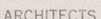
The image displays a technical drawing or blueprint of what appears to be the interior layout for a room or a set of rooms. The drawing is very detailed and shows multiple elevations of interior walls with indications of doors, screens, and lighting placement. Dimensions are provided throughout the drawing, specifying lengths and distances between various elements in feet and inches. Annotations on the drawing are labeled "Dining Alcove S.E.," "Dining Room S.E.," "Living Room S.E.," "Living Room N.W.," and "Study N.W." These labels suggest that the blueprint covers different sections of a residential space.
At the bottom of the drawing, there is a note that reads, "All dimensions shown here must be verified on the job, and any deviations should be followed up by a letter to this office explaining same. Work can then proceed as will be decided on job measurements."
In the bottom right corner, there is text indicating the architects associated with the blueprint, "Walter Gropius & Marcel Breuer associated architects, cambridge, mass." with a reference to a project or client named "Jerome Frank House" and revisions dated "2/3/40." There is also the name of an office that might have created the drawing or been involved in overseeing the work, "Ritchey & Mitchell Registered Architects Pittsburgh, Penna." An additional note on the bottom left side states that the contractor must verify all dimensions on the job and report any discrepancies to the architect, ensuring that the construction is done according to the technical specifications.
In the corner, there is a drawing number or file indicator "222" and a scale provided as "1/4" = 1'-0"" which means that one quarter inch on the drawing is equivalent to one foot in real dimensions. This kind of blueprint is typical for architects and contractors to communicate detailed plans for construction or renovation work.
Created by gpt-4o-2024-05-13 on 2025-03-06
The image appears to be an architectural drawing related to interior construction, specifically detailing the dimensions and layout of different rooms and lighting fixtures. The drawing includes details for a "Dining Alcove S.E.," "Dining Room S.E.," "Living Room S.E.," "Living Room N.W. #62," and "Study N.W. #77."
At the top left, there's a note reminding the contractor to verify all dimensions on-site and to report any discrepancies to the architects. Towards the center, another note mentions that all dimensions shown must be verified on the job and that the drawing should be followed closely, especially regarding conditions of lights, as final measurements may depend on actual job measurements.
The drawing is labeled with a title block at the bottom right, which includes the architects' information: Walter Gropius & Marcel Breuer, associated architects from Cambridge, Mass. It also includes the details of the project:
- Date: 2/13/40
- Job: Special Frank House, Pitts. PA
- Drawn by: Kenwow
- Subject: Installation of curtain light fixtures
- Scale: 1/2" = 1'0"
- Drawing number: 222
The architects involved, Walter Gropius and Marcel Breuer, were prominent figures in modernist architecture, suggesting that this drawing is part of a significant architectural work.
Anthropic Claude
Created by claude-3-haiku-20240307 on 2024-12-31
This image appears to be a set of architectural plans or drawings. It contains detailed dimensions and measurements for various rooms and spaces, including a dining room, living room, and study. The dimensions and layout of these rooms are clearly specified, with precise numerical values provided. The image also includes some handwritten notes and instructions, likely provided by the architects or contractors involved in the project. Overall, this document seems to be a technical blueprint or design schematic related to a residential or commercial building project.
Created by claude-3-opus-20240229 on 2024-12-31
The image shows an architectural plan for a single-story residential building. The plan displays the layout and dimensions of various rooms including living rooms, dining rooms, a study, and a living room display area. The rooms are labeled with their dimensions and square footage. The plan also includes handwritten notes at the bottom mentioning revisions to the design. In the bottom right corner, there is an architectural firm logo for "Ritchey & Mitchell Registered Architects" in Pittsburgh, Pennsylvania, along with a project number 222.
Created by claude-3-5-sonnet-20241022 on 2024-12-31
This is an architectural drawing showing detailed elevation plans for various rooms including a dining alcove, dining room, living room, and study. The drawing includes precise measurements and dimensions for what appear to be wall sections or built-in fixtures. At the top, there are measurements for the dining alcove and dining room, with dimensions noted in feet and inches. Below these are elevation views for the living room and study areas. The drawing has a professional appearance with title blocks in the bottom right corner indicating it was produced by Walter Gropius & Marcel Breuer (associated architects from Cambridge, Mass.) and Ritchey & Mitchell (registered architects from Pittsburgh, PA). The drawing appears to be numbered 222 and includes notes about contractor verification of dimensions. The style is typical of mid-century architectural documentation, with clean lines and precise technical drafting.
Meta Llama
Created by us.meta.llama3-2-11b-instruct-v1:0 on 2025-03-17
The image is a technical drawing of a building, specifically the floor plan and elevations of a living room and dining room. The drawing is hand-drawn on white paper with black ink and includes various measurements and notes.
Floor Plan:
- The floor plan shows the layout of the living room and dining room, including the location of doors, windows, and furniture.
- The living room is located on the left side of the drawing, with a large window on the front wall and a door leading to the hallway.
- The dining room is located on the right side of the drawing, with a large window on the front wall and a door leading to the kitchen.
Elevations:
- The elevations show the exterior of the building, including the walls, windows, and doors.
- The elevations are drawn from different angles, including the front, side, and rear of the building.
- The elevations include measurements for the width and height of the building, as well as the size and location of the windows and doors.
Notes:
- The drawing includes several notes and annotations, including measurements, labels, and symbols.
- The notes provide additional information about the building, such as the location of plumbing and electrical fixtures, and the type of materials used in the construction.
Overall:
- The drawing provides a detailed and accurate representation of the building's design and layout.
- The use of measurements and notes adds an extra layer of detail and clarity to the drawing, making it easier to understand and interpret.
- The drawing appears to be a high-quality, professional-grade technical drawing, suggesting that it was created by an experienced architect or engineer.
Created by us.meta.llama3-2-90b-instruct-v1:0 on 2025-03-17
This image depicts a technical drawing or blueprint, likely for an architectural project. The document features a series of lines and measurements, accompanied by handwritten notes and labels in pencil. The text is too small to be legible, but it appears to include dimensions, room names, and other relevant details.
In the bottom-right corner, a rectangular box contains the names "Walter Gropius & Marcel Breuer" alongside the title "Associated Architects, Cambridge, Mass." Below this, another box displays the name "Ritchey & Mitchell" with the subtitle "Registered Architects Pittsburgh, Penna." A third box in the bottom-right corner bears the number "222."
The background of the document is a light beige color, resembling aged paper. The overall appearance suggests that this is a vintage or historical document, possibly from the mid-20th century.
Amazon Nova
Created by amazon.nova-lite-v1:0 on 2025-02-25
The image appears to be an architectural blueprint or construction plan. Here is a detailed description of the image:
The blueprint consists of multiple sections, with text and diagrams arranged in a structured format. The text is in a smaller font, providing details and specifications related to the construction project. The diagrams, drawn in a larger font, illustrate various aspects of the building's design and layout.
In the top section, there is a note stating that the contractor must verify all dimensions on the job site and report any discrepancies to the architect. This emphasizes the importance of accuracy and adherence to the specified plans.
The blueprint contains several labeled sections, such as "Dining Room," "Living Room," "Bedroom," and "Study." Each section is accompanied by a corresponding diagram that shows the dimensions and layout of the respective room.
The dimensions are provided in both feet and inches, allowing for precise measurements. For example, the "Dining Room" section shows dimensions like "14'-6" x 15'-4"" and "12'-0" x 14'-0"" for different areas within the room.
The blueprint also includes notes and annotations related to specific elements of the design. For instance, there is a note mentioning "S.E. 11'-0"" in the "Dining Room" section, which could refer to a specific feature or measurement within that area.
In the bottom section, there is a table or list that appears to summarize the key details of the project. It includes information such as the project name, architect's name, and other relevant details.
Overall, the blueprint provides a comprehensive visual representation of the building's design, layout, and dimensions, serving as a crucial document for the construction process.
Created by amazon.nova-pro-v1:0 on 2025-02-25
The image is a blueprint of a building with a title, "PITTSBURGH PENNA." The blueprint is divided into several sections, each representing a different part of the building. There are dimensions and measurements on the blueprint, along with notes and annotations. The blueprint also includes a legend that explains the different symbols and abbreviations used on the drawing. The blueprint appears to be a detailed plan for the construction of a building, with specific instructions for the placement of walls, doors, windows, and other features.
Text analysis
Amazon