Machine Generated Data
Tags
Color Analysis
Feature analysis
Amazon
| Document | 94.1% | |
Categories
Imagga
| text visuals | 100% | |
Captions
Microsoft
created on 2018-03-22
| a close up of text on a white background | 77.5% | |
| a close up of text on a black background | 71.1% | |
| a close up of text on a white surface | 71% | |
OpenAI GPT
Created by gpt-4o-2024-05-13 on 2025-03-07
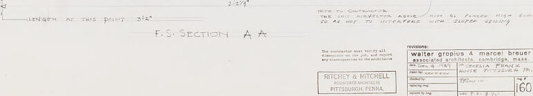
The image is a technical drawing or blueprint that appears to detail a structural or architectural component. It includes various sectional views and plans, likely related to a specific part of a building or construction project. Key elements include: 1. Several sectional diagrams are labeled, one as "F.S. SECTION A-A," indicating a cross-sectional view. 2. A smaller plan view labeled "PLAN OF VEST. 021 – 1/2"=1'−0" SHOWING DISPLAY IN CEILING". 3. The drawing contains detailed notes for contractors such as "NOTE: LIGHTING CONTRACTOR SHALL FURNISH THE ARCHITECTS WITH 2 SHOP DRAWINGS FOR HIS APPROVAL". 4. Additional notations include instructions on the placement and application of materials, including references to plaster, acoustic plaster, framing, and a plaster recess. 5. Measurement specifications are provided, such as "228 3/4" and "length at this point 28 1/2'". 6. There's a detail box containing project details including "RICHEY & MITCHELL, Associate Architects, Pittsburgh Penna" and "WALTER GROPIUS & MARCEL BREUER, Associated Architects, Cambridge, Mass". This drawing is likely a part of a larger set of construction documents needed for understanding specific construction details related to roofing, framing, vestibule ceiling display arrangements, and materials specifications.
Created by gpt-4 on 2025-03-07
This image appears to be a technical drawing, specifically an architectural design of a detail called "Vest. 224 1/2" = 1'-0"." The drawing presents a plan view and a section view labeled as "F.S. SECTION A-A." The level of detail suggests this might be for a specific construction feature, such as a vestibule, given the label "Vest." In the plan view on the right, we can see an overhead representation of what appears to be an inset or niche, with demarcated dimensions (like 5'6"). The section view on the left provides a side profile of a structural detail or portion of a building, showcasing various construction features such as footing, foundation, and baseplate. The note on the left side indicates that the "Lighting fixture specified shall furnish the Architect with 3 Shop Drawings for his approval." Various dimensions and construction notes are also included. At the bottom right of the drawing, there's a stamp indicating the names "Walter Gropius & Marcel Breuer, Associated Architects" from Cambridge, Massachusetts, which signifies the architects who either created the drawing or for whom the drawing was made. The drawing also has a stamp for "Ritchey & Mitchell," located in Pittsburgh, Pennsylvania. The set of drawings is numbered as 160, and there is a note for revisions by someone whose name has been partially obscured.
Anthropic Claude
Created by claude-3-haiku-20240307 on 2024-12-31
The image appears to be an architectural or engineering drawing or diagram. It shows a plan or cross-section view of some kind of structure or system, with various labels and measurements. The drawing includes detailed technical specifications and dimensions, but does not contain any human faces or identifiable individuals.
Created by claude-3-opus-20240229 on 2024-12-31
The image shows an architectural plan or blueprint labelled "FS Section A-A". It depicts a cross-section view of what appears to be a vessel or maritime structure, given the curved hull shape at the bottom. The plan provides dimensions and labels for various components such as the "Outer Shell", "Floors", "Under Deck", and "Coaming". A small detailed section in the upper right is captioned "Plan of Vesl. 2x2 - Mx 18". In the bottom right corner is a title block with fields for number, scale, date and other details about this "Water Grouting & Mercel Braust" plan, which seems to be related to some grouting or cement application in a shipbuilding or ship repair context based on the technical naval architecture nature of the drawing.
Created by claude-3-5-sonnet-20241022 on 2024-12-31
This appears to be an architectural drawing or technical blueprint. It shows both a plan view and a cross-sectional view (labeled as "F.S. SECTION A-A") of what appears to be some kind of built structure. The drawing includes various measurements and annotations, and in the bottom right corner there are title blocks with information about the architects or designers (Walter Gropius & Marcel Breuer). The plan view shows what looks like a "V" shaped or curved layout, while the section view shows various levels and structural details. The drawing is done in a professional architectural style with clean lines and precise measurements. The document appears to be from Ritchey & Mitchell of Pittsburgh, Pennsylvania, as indicated in the title block.
Meta Llama
Created by us.meta.llama3-2-11b-instruct-v1:0 on 2025-03-17
The image presents a detailed architectural drawing of a building's floor plan, featuring a combination of handwritten notes and precise measurements. The drawing is rendered in black ink on white paper, with the majority of the text written in pencil. **Key Features:** * **Floor Plan:** The drawing depicts the floor plan of a building, showcasing its layout and design. * **Handwritten Notes:** Throughout the drawing, there are handwritten notes that provide additional information about the building's features and specifications. * **Precise Measurements:** The drawing includes precise measurements, ensuring accuracy and clarity in the design. * **Black Ink and Pencil:** The drawing is rendered in black ink on white paper, with the majority of the text written in pencil. * **Architectural Drawing:** The image is an architectural drawing, likely created by an architect or designer to visualize and communicate the building's design. **Summary:** The image presents a detailed architectural drawing of a building's floor plan, featuring a combination of handwritten notes and precise measurements. The drawing is rendered in black ink on white paper, with the majority of the text written in pencil. The image provides a clear and accurate representation of the building's design, making it a valuable resource for architects, designers, and builders.
Created by us.meta.llama3-2-90b-instruct-v1:0 on 2025-03-17
This image presents a detailed architectural drawing of a building's section, showcasing the design and layout of the structure. The drawing is rendered in black ink on white paper, with various notes and labels scattered throughout. **Key Features:** * **Section AA:** The main focus of the drawing, Section AA, is prominently displayed in the center of the image. It appears to be a cross-section of the building, highlighting the relationships between different components such as walls, floors, and ceilings. * **Notes and Labels:** Throughout the drawing, numerous notes and labels provide additional information about the design. These include measurements, material specifications, and construction details. * **Scale and Dimensions:** The drawing includes a scale and dimensions, allowing viewers to understand the size and proportions of the building. * **Architectural Details:** The drawing showcases various architectural details, such as windows, doors, and columns. These elements are carefully rendered to provide a clear understanding of the building's design. **Overall Impression:** The image presents a comprehensive and detailed architectural drawing of a building's section. The use of black ink on white paper creates a clean and professional appearance, while the numerous notes and labels provide valuable information about the design. The drawing effectively communicates the relationships between different components of the building, making it an essential tool for architects, engineers, and contractors involved in the construction process.
Amazon Nova
Created by amazon.nova-lite-v1:0 on 2025-02-26
This image is a technical architectural drawing of a building's vertical ventilation system, likely from the 1930s. The drawing shows a plan view of the ventilation system, with various components labeled. The system includes a vertical shaft, a fan, and ducts that connect to different parts of the building. The drawing also includes notes and measurements, indicating the dimensions and specifications of the system. The drawing is signed by the architect, Walter Gropius, and includes the date and location of the project.
Created by amazon.nova-pro-v1:0 on 2025-02-26
The image is a technical drawing of a section of a building. The drawing is labeled as "F.S. SECTION A A" and includes various annotations and dimensions. The drawing depicts a vertical section of the building, showing the arrangement of the walls, floors, and other structural elements. The drawing includes details such as the thickness of the walls, the height of the floors, and the location of doors and windows. The drawing also includes a note that reads "PLAN OF VEHICLE 024-1/2-110 SHOWING SLOPY IN CENT." This note likely refers to a plan or diagram of a vehicle that is related to the building section shown in the drawing. The drawing is a technical document used by architects, engineers, and construction professionals to communicate the design and construction details of a building.
Text analysis
Amazon