Machine Generated Data
Tags
Color Analysis
Feature analysis
Amazon

| Document | 56.3% | |
Categories
Imagga
| text visuals | 100% | |
Captions
Microsoft
created on 2018-03-22
| a close up of text on a white background | 80.8% | |
| a close up of text on a black background | 76.3% | |
| a screenshot of text | 76.2% | |
OpenAI GPT
Created by gpt-4 on 2025-03-06
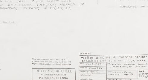
The image shows a technical architectural drawing or blueprint. On the left side of the drawing, there's a cross-section diagram detailing a wall intersection, with annotations such as "storage room," existing conditions, and specific measurements. On the right side of the drawing, there is an elevation of what appears to be a piece of furniture or a fixture, again with detailed notations and measurements. Below the main drawing area, there is a box with text that credits Walter Gropius & Marcel Breuer as the associated architects from Cambridge, Massachusetts, and also mentions Ritchey and Mitchell, Pittsburgh architects. There is a date and various notes in the revisions box, suggesting that this is a working document which has undergone updates and changes. The style of the drawing and handwriting suggests that it is a professional draft produced by architects or engineers as part of a broader set of construction or design plans.
Created by gpt-4o-2024-05-13 on 2025-03-06
This image is a detailed architectural drawing, labeled as a section and elevation of the southwest wall of a third floor. The drawing shows the methods for mounting outlets numbered #20, 29, and 30. It includes technical notes, measurements, and specifications for construction. Key elements depicted in the drawing include: - Cross-sections and elevations of the wall - Technical information for installation by electrical contractors - Specifics such as "ex. lath", "storage room", and other construction details - Notations regarding brass plates and finishes on the outlet by electrical contractors - Measurement details indicating dimensions, such as "1 3/8" brass cover plates mounted to inner frame by others - It also lists the architecture firms involved: "Ritchey & Mitchell, Architects" from Pittsburgh, Pennsylvania, collaborated with "Walter Gropius & Marcel Breuer, Associated Architects" from Cambridge, Massachusetts. - There is an outlined section for revisions and dates, signed by Kenyon in December 1950 and detailing a specific job for the Pittsburgh Housing Authority, East Liberty Project PA-2-22, Sheet No. 163. Enclosing this layout are technical notes that may include material specifications and precise construction instructions detailed by the architects.
Anthropic Claude
Created by claude-3-haiku-20240307 on 2024-12-30
This image appears to be an architectural or engineering drawing. It shows a sectional view or plan of a building structure, with various dimensions, annotations, and details noted. The drawing includes a title and details about the architects or engineers who produced it. There are no human faces or identifiable individuals visible in the image.
Created by claude-3-opus-20240229 on 2024-12-30
The image shows an architectural drawing or blueprint. It depicts details and measurements for what appears to be a storage room or closet. The drawing includes a floor plan view showing the dimensions of the room, as well as an elevation view of one of the walls with shelving. Handwritten notes provide additional specifications about the materials to be used, such as plywood sheeting for the shelves and walls. A small table in the bottom right corner lists the client name (Walter Gropius & Marcel Breuer), project name, drawing number, scale, and date.
Created by claude-3-5-sonnet-20241022 on 2024-12-30
This is an architectural drawing showing a detailed section view through a south-west wall. The drawing appears to be a technical blueprint or construction document that includes specifications for storage room space and various architectural elements. It contains precise measurements and notations, typical of professional architectural plans. The drawing has title blocks and architect information at the bottom, indicating it was created by an architectural firm in Pittsburgh, Pennsylvania. The level of detail suggests this is likely a construction document used for building purposes rather than a conceptual sketch. The cross-sectional view shows wall construction details and mounting specifications.
Meta Llama
Created by us.meta.llama3-2-11b-instruct-v1:0 on 2025-03-13
The image presents a detailed architectural drawing of a building's interior, specifically focusing on the south wall of the third floor. The drawing is rendered in black and white, with handwritten notes and measurements in pencil. **Key Features:** * **South Wall of Third Floor:** The drawing centers on the south wall of the third floor, providing a comprehensive view of the space. * **Storage Room:** A storage room is located on the left side of the drawing, with its dimensions and layout clearly indicated. * **Elevation of Wall:** The elevation of the wall is shown on the right side of the drawing, offering a detailed view of the wall's structure and features. * **Handwritten Notes and Measurements:** Pencil-written notes and measurements are scattered throughout the drawing, providing additional information about the space. * **Architectural Details:** The drawing includes various architectural details, such as doorways, windows, and other features that contribute to the overall design of the space. * **Scale and Dimensions:** The drawing includes a scale and dimensions, allowing for precise measurements and calculations. * **Revisions:** The drawing includes revisions, indicating that it has undergone changes and updates. * **Signatures:** The drawing bears signatures from Walter Gropius and Marcel Breuer, associated architects from Cambridge, Mass. * **Company Information:** The drawing also includes company information, including the name "Ritchey & Mitchell" and the location "Pittsburgh, Penna." **Overall Impression:** The image presents a detailed and informative architectural drawing that provides a comprehensive view of the south wall of the third floor. The inclusion of handwritten notes and measurements adds a personal touch, while the architectural details and revisions demonstrate a high level of attention to detail. The signatures and company information suggest that the drawing is a professional and official document.
Created by us.meta.llama3-2-90b-instruct-v1:0 on 2025-03-13
The image depicts a technical drawing of a building's wall section, likely created by an architect or engineer. The drawing is rendered in black ink on white paper and features a detailed cross-section of the wall, including its various components such as the foundation, walls, windows, doors, and roof. The drawing also includes notes and annotations that provide additional information about the design and construction of the building. These notes may include details about the materials used, the dimensions of the various components, and any special features or requirements that need to be considered during construction. Overall, the image provides a clear and detailed visual representation of the building's design and construction, which can be useful for architects, engineers, contractors, and other professionals involved in the building process.
Amazon Nova
Created by amazon.nova-lite-v1:0 on 2025-01-13
The image appears to be an architectural drawing or blueprint, depicting a section of a building's structure. The drawing shows a wall section, with details such as the dimensions, materials, and construction techniques. The wall section is labeled as "SECTION THUS SOUTH WEST WALL OF 3RD FLOOR SHOWING METHOD OF MOUNTING OUTLETS # 28, 29, 30." This suggests that the drawing is focused on the installation of electrical outlets on the third floor of the building. The drawing includes various annotations and notes, indicating the materials and methods used in the construction. For example, there are references to "BRASS 2000" and "CARBON STEEL," which likely refer to the types of materials used in the wall section. There are also notes about the placement of electrical conduits and the dimensions of the wall section. The drawing is labeled as "RITCHEY & MITCHELL," indicating that it was created by these architectural firms. The drawing also includes a revision history, showing that there have been changes made to the original drawing over time. Overall, the image appears to be a technical drawing used by architects, engineers, and construction professionals to plan and execute the construction of a building. The detailed annotations and notes provide important information about the materials, dimensions, and construction techniques used in the wall section depicted in the drawing.
Created by amazon.nova-pro-v1:0 on 2025-01-13
The image is a detailed architectural drawing of a section of a building. It is a technical blueprint with various annotations and measurements. The drawing includes a section through the south wall, showing the method of mounting outlets. There are dimensions and labels indicating specific areas and components of the structure. The drawing is marked with revisions and includes the names of the architects and the company responsible for the design.
Text analysis
Amazon