Machine Generated Data
Tags
Color Analysis
Categories
Imagga
| text visuals | 100% | |
Captions
Microsoft
created by unknown on 2018-03-22
| a close up of text on a white background | 78.3% | |
| a close up of text on a black background | 72.9% | |
| a close up of text on a white surface | 72.8% | |
Clarifai
created by general-english-image-caption-blip on 2025-05-11
| a photograph of a drawing of a plan for a house | -100% | |
OpenAI GPT
Created by gpt-4 on 2025-03-08
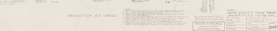
This image displays a series of architectural drawings and details. The drawings seem to be technical, mechanical drafts that show different views and sections of what is labeled as "Recreation Rm. Cases," possibly referring to casework or built-in elements for a recreation room within a building.
To the top left, we see an elevation view labeled "Front Elevation," which presents the front-facing view of the case or cabinetry. There are dimensions and notes provided to guide the construction or installation, including details such as "1/2" Plywood Back", "Birch Dowels" etc.
Below that is another drawing labeled "Plan," which is a top-down view of the casework, and "Plan-Section," which seems to cut through the casework to show the internal structures or shelving.
On the right side, a series of detailed sectional views are shown, labeled "Section A-A," "Partial Section A-A," and "Section B-B," each displaying different parts of the casework in more detail.
The architectural drafting style indicates this is a professional and technical document, most likely used for the construction of interior architectural elements.
In the bottom right, there's a block of text with "Ritchey & Mitchell Pittsburgh, Penna." which could signify the firm that created the drawings, and another mention that includes "Walter Gropius - Marcel Breuer and Associated Architects, Cambridge, Mass" that likely indicates design consultation or collaboration with notable architects.
The nature of the line work, the annotations, and the style of the drafting all point to this being mid-20th-century work, judging by the manual drafting style and typology of the technical drawings, which might have been created before the widespread use of computer-aided design (CAD) programs.
Created by gpt-4o-2024-05-13 on 2025-03-08
The image depicts an architectural blueprint of a section of a building, specifically identified as "Recreation Rm. Cases". The drawing contains detailed plans and sections of built-in casework, likely for a recreational room.
In the lower-left corner, there is a title block that attributes the design to "Walter Gropius & Marcel Breuer" as associated architects in Cambridge, Massachusetts. "Ritchey & Mitchell" are mentioned as the architects and engineers based in Pittsburgh, Pennsylvania. The drawing is labeled with a project number "239".
The blueprint includes multiple views:
- Front Elevation: A frontal view of the casework, showing dimensions and details of the design.
- Plan: A top-down view of the layout and structure, showcasing precise measurements and spatial arrangements.
- Section Views: Multiple section views (A-A, B-B, etc.) give detailed cross-sections of different parts of the structure with exact measurements.
- Partial Sections: Enlarged detailed views of specific sections to highlight intricate aspects of construction and joinery.
The drawing is heavily annotated with notes, dimensions, and instructions to guide the construction process, ensuring accuracy and fidelity to the architects' designs.
Anthropic Claude
Created by claude-3-haiku-20240307 on 2024-12-30
This image appears to be an architectural blueprint or technical drawing. It contains various diagrams, plans, and sketches that seem to detail the layout and specifications of a building or structure. The drawings include floor plans, cross-sections, and other technical details, suggesting this is a professional design or construction document. The level of detail and precise technical information suggests this is likely an engineering or architectural drawing used for the purpose of planning and constructing a built environment.
Created by claude-3-opus-20240229 on 2024-12-30
The image shows an architectural floor plan or blueprint for what appears to be a residential building or house. The plan includes detailed dimensions, room layouts, and notes about various construction elements and materials. Key features visible include a front porch area, main living spaces, bedrooms, bathrooms and a kitchen. The blueprint style drawing uses thin lines on a light background to depict the walls, doors, windows and other structural components in a precisely measured and scaled manner typical of architectural plans used for construction.
Created by claude-3-5-sonnet-20241022 on 2024-12-30
This appears to be an architectural drawing or blueprint, likely from a Gropius & Breuer project. The drawing shows various plans and sections for what's labeled as "Recreation Rm. Cases" for a project in Pittsburgh, Pennsylvania. The document includes multiple detailed views:
- Front elevations
- Plan views
- Cross-sections
- Detail sections
The drawings are technical in nature, showing measurements and construction details for what appears to be built-in cabinetry or storage cases in a recreation room. The plans are drawn to scale and include detailed dimensions and annotations. The drawing style is characteristic of mid-century architectural documentation, with clean lines and precise technical detailing. In the bottom right corner, there appears to be a title block with project information and what looks like an architectural firm's details.
The plans show both horizontal and vertical sections of the casework, providing comprehensive information for construction purposes. The level of detail suggests this was a working drawing meant for actual construction implementation.
Meta Llama
Created by us.meta.llama3-2-11b-instruct-v1:0 on 2025-03-14
The image is a technical drawing of a building's floor plan and elevation, showcasing the architectural design and layout of the structure.
Floor Plan:
- The floor plan is divided into several sections, each representing a different level or area of the building.
- The sections are labeled with letters and numbers, indicating the location and purpose of each space.
- The floor plan includes various symbols and notations, such as arrows, lines, and text, which provide additional information about the building's features and components.
Elevation:
- The elevation drawing shows the exterior of the building, including its walls, windows, doors, and roof.
- The elevation is depicted from a specific angle, allowing the viewer to visualize the building's appearance from that perspective.
- The elevation includes measurements and labels, providing detailed information about the building's dimensions and features.
Additional Details:
- The drawing includes a key or legend, which explains the symbols and notations used throughout the plan.
- There are also notes and comments written in the margins, likely providing additional context or explanations for the design decisions made by the architect.
- The drawing appears to be hand-drawn, with pencil marks and corrections visible throughout the document.
Overall:
- The technical drawing provides a comprehensive overview of the building's design and layout, allowing architects, engineers, and contractors to understand the project's requirements and specifications.
- The level of detail and precision in the drawing suggests that it was created for a specific purpose, such as construction or renovation, and is intended to be used as a reference guide for the project team.
Created by us.meta.llama3-2-90b-instruct-v1:0 on 2025-03-14
The image presents a collection of architectural drawings, likely created for a building project. The drawings are rendered in black ink on a white background, with some sections featuring handwritten notes and labels.
Key Features:
- Multiple Drawings: The image contains several drawings, including floor plans, elevations, and sections, which provide a comprehensive view of the building's design.
- Handwritten Notes: Many of the drawings feature handwritten notes and labels, indicating that the architect or designer has added additional information to clarify specific details.
- Scale and Measurements: The drawings include scale indicators and measurements, allowing viewers to understand the proportions and dimensions of the building.
- Architectural Details: The drawings showcase various architectural elements, such as windows, doors, walls, and roofs, which provide insight into the building's design and functionality.
- Legibility: While the drawings are detailed and informative, some of the handwritten notes may be difficult to read due to their small size or illegible handwriting.
Overall Impression:
The image suggests that the architectural drawings are part of a larger project, possibly a residential or commercial building. The level of detail and attention to scale and measurements indicate that the drawings are intended for construction or planning purposes. The presence of handwritten notes and labels adds a personal touch, suggesting that the architect or designer has invested time and effort into creating a comprehensive and accurate representation of the building's design.
Amazon Nova
Created by amazon.nova-lite-v1:0 on 2025-01-11
The image is a technical drawing of architectural plans, likely for a building project. The drawing is labeled "Recreation RM Cases" and includes various sections and elevations. The plans are detailed with dimensions, annotations, and labels indicating different parts of the structure. The drawing features a front elevation, partial section, and plan sections, showing the layout and dimensions of the space. The text and numbers are in a small, readable font, and the drawing is neatly organized, with clear lines and labels.
Created by amazon.nova-pro-v1:0 on 2025-01-11
The image shows a blueprint of a building, possibly a house. It is divided into several sections, each labeled with a letter. The blueprint includes a front elevation, plan section, and partial sections labeled as A, B, and C. The blueprint also includes measurements and dimensions of the rooms and walls. The blueprint is dated and includes the names of the architects who designed the building.
Google Gemini
Created by gemini-2.0-flash on 2025-05-08
Here's a description of the image:
The image shows an architectural blueprint on a light tan background. It's likely a scanned or digitally reproduced drawing, given its monochrome appearance and fine linework. The blueprint details the construction plans for "Recreation Rm. Cases," which appears to be a storage or display case design for a recreation room.
The blueprint includes several views of the case from different perspectives, with hand-drawn dimensions and notes. These views include:
- Front Elevation: Shows the appearance of the case from the front.
- Plan: A top-down view illustrating the dimensions and layout of the case.
- Plan-Section: A horizontal cut through the case, revealing the interior structure.
- Section (A-A), Partial Section (A-A (Back), Partial Section (A-A (Front)): Vertical cuts at specific points, indicated by 'A-A', showcasing the internal construction and joinery details.
- Section (B-B): An additional vertical cut showing alternative construction details.
Handwritten notes and dimensions are scattered across the blueprint, providing specific instructions on materials, measurements, and construction methods. At the bottom right corner, there's a title block indicating the architects as "Walter Gropius & Marcel Breuer, Associated Architects, Cambridge, Mass." with the firm name "RITCHEY & MITCHELL" and location "Pittsburgh, Penna." The title block is filled with other information such as revisions, and approval initials.
Created by gemini-2.0-flash-lite on 2025-05-08
This is a detailed architectural drawing, likely a blueprint or technical drawing. It appears to be a design for "RECREATION RM. CASES". It features several views and sections of the object, including:
- Front Elevation: A view of the case from the front.
- Plan: A top-down view, showing the layout of the case.
- Plan-Section: A view showing the case cut through at a certain point, exposing the interior.
- Section (A-A) & (B-B): Sectional drawings through different points, providing details of the construction and materials.
- Partial Sections: Sections with more detail to help with assembly.
The drawing includes dimensions, annotations with materials, and construction details (like "1" plywood top", "2x2 block"). The style and detail level suggest it was created for construction purposes. The drawing is signed at the bottom by "RITCHEY & MITCHELL" and "Walter Gropius & Marcel Breuer".
Mistral Pixtral
Created by us.mistral.pixtral-large-2502-v1:0 on 2025-05-30
The image is an architectural drawing, specifically a set of blueprints for a building labeled "Recreation RM Cases." The drawing is detailed and includes various views and sections of the building, such as front elevation, rear elevation, and a section view.
Here are the key components visible in the drawing:
Front Elevation:
- This view shows the facade of the building, including the layout of windows, doors, and other architectural features.
- Dimensions and measurements are provided to indicate the size and placement of elements.
Rear Elevation:
- This view shows the back side of the building, detailing the rear facade, including windows and other structural elements.
- Similar to the front elevation, dimensions and measurements are included.
Section View:
- This view provides a cross-sectional perspective of the building, showing the internal structure and layout.
- It includes details such as the floor levels, roof structure, and internal spaces.
Details and Annotations:
- The drawing includes various annotations and notes that provide additional information about the design and construction.
- These notes may include material specifications, construction details, and other relevant information.
Architects and Firm Information:
- The drawing is credited to Walter Gropius and Marcel Breuer, both renowned architects.
- The architectural firm listed is "TITCHEY & MITCHELL" from Pittsburgh, Pennsylvania.
- The drawing is dated March 1940.
Scale and Measurements:
- The drawing includes a scale for reference, allowing for accurate interpretation of the dimensions.
- Various measurements are provided throughout the drawing to specify the sizes of different elements.
Overall, the image is a comprehensive architectural blueprint that provides detailed information about the design and construction of a recreational room or building.
Text analysis
Amazon