Machine Generated Data
Tags
Color Analysis
Feature analysis
Amazon

| Rug | 71.3% | |
Categories
Imagga
| text visuals | 99.6% | |
| paintings art | 0.3% | |
Captions
Microsoft
created on 2018-03-22
| a close up of text on a whiteboard | 70% | |
| a close up of a whiteboard | 69.8% | |
| close up of text on a whiteboard | 66.9% | |
OpenAI GPT
Created by gpt-4o-2024-05-13 on 2025-03-07
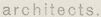
The image is a technical architectural drawing detailing various door sections. The drawing features multiple cross-sectional views of different door designs, including their labels and specific measurements. The sections are meticulously sketched with several lines representing the door structure, frames, and surrounding walls or floors. The labels include designations like "DOOR #201," "DOOR #202," "DOOR 220 (EXTERIOR)," and "DOOR #301," alongside other notations such as "JAMBS" and "HEAD (WITH TRANSOM)." The drawing is produced by an architectural firm, Ritchey & Mitchell Architects from Pittsburgh, Pennsylvania, for Walter Gropius & Marcel Breuer Associated Architects, based in Cambridge, Massachusetts. Additional handwritten notes and revisions specify detailed instructions, such as "NOTES: DOORS 1 3/4" X 2 1/2" HT. SOLID CONSTRUCTION MACHINING OF LOCK EDGE TRANSOM OF 'TREATY, 10'." The drawing number is indicated as "206," and the sheet is part of a broader set of architectural plans.
Created by gpt-4 on 2025-03-07
The image shows a technical architectural drawing or blueprint that consists of several detailed plans for door constructions. Each panel on the drawing is labeled with "DOOR" followed by a number, which probably corresponds to a specific design or location in a building plan. These labels range from "DOOR #201" to "DOOR #206," indicating multiple door designs are presented. The plans include cross-sections showing the side profiles of each door. Such details commonly display the door's dimensions, the materials used, and the way they should be fitted into the wall structure. The hatch marks on certain parts of the drawings suggest different materials or components, as is typical in architectural plans to differentiate between various elements. In the bottom right-hand corner, there's a title block with the words "RITCHEY & MITCHELL, PITTSBURGH, PENNA" indicating the name of an architecture or engineering firm likely responsible for this drawing. Below are the names "Walter Gropius & Marcel Breuer" in typeset, suggesting the involvement of these two well-known architects in the design. The title block contains additional information that is a bit too small to read, but generally includes the project name, drawing number, date, scale, and other standard project details. On a first look, the paper appears to be aged, with some discoloration and creases that suggest it is an actual physical drawing rather than a digital reproduction. It's likely a part of an architectural archive or a collection of historical building plans.
Anthropic Claude
Created by claude-3-haiku-20240307 on 2024-12-31
The image appears to be a series of architectural drawings or plans. It shows various geometric shapes and configurations, likely representing different floor plans or design elements for a building or structure. The drawings contain measurements, labels, and other technical notations that suggest they are part of an engineering or architectural design document. Without being able to identify any individuals, the image seems to depict the technical details and spatial arrangements of a proposed or planned structure.
Created by claude-3-opus-20240229 on 2024-12-31
The image shows an architectural drawing or blueprint. It depicts the floor plans for what appears to be a residential building, likely a house or apartment. The plans show the layout and dimensions of various rooms including a living room, dining room, kitchen, and bedrooms. Notes and dimensions are provided throughout the drawing. The blueprint title in the bottom right indicates this is a design by "Ritchey & Mitchell, Architects" in Pittsburgh, Pennsylvania for a "walter dropkin & marcel breuer" project.
Created by claude-3-5-sonnet-20241022 on 2024-12-31
This image appears to be an architectural drawing or blueprint showing various door details and sections. The drawing includes multiple door elevations or profiles, each labeled with a door number (like "DOOR #201", "DOOR #202", etc.). The drawings are technical in nature, showing the dimensions and construction details of different door types in plan and elevation views. The document appears to be from an architectural firm called "RITCHEY & MITCHELL" from Pittsburgh, Pennsylvania. At the bottom right, there's a title block with what appears to be project information. The drawings are done in a professional drafting style with clean lines and proper architectural conventions. The details show variations in door depths, jamb conditions, and frame configurations. This type of drawing would typically be used during construction to specify exact door requirements and installation details.
Meta Llama
Created by us.meta.llama3-2-11b-instruct-v1:0 on 2025-03-14
The image presents a detailed architectural floor plan, showcasing the layout of a building's interior spaces. The plan is drawn on a piece of paper with a light beige color and features a grid pattern, indicating the location of various rooms, doors, and corridors. **Key Features:** * **Grid Pattern:** The floor plan is divided into a grid, with each square representing a specific area of the building. * **Room Labels:** Each room is labeled with a unique identifier, such as "DOOR *201" or "DOOR *202." * **Door Locations:** The locations of doors are marked on the plan, providing a clear understanding of the building's circulation paths. * **Corridor Layout:** The corridors are depicted as narrow, rectangular spaces that connect the various rooms. * **Room Sizes:** The sizes of the rooms are indicated by the number of squares they occupy in the grid. * **Scale:** The scale of the plan is not explicitly stated, but it appears to be a 1:100 or 1:50 scale, given the level of detail and the size of the rooms. **Additional Details:** * **Architectural Style:** The building's architectural style is not immediately apparent from the floor plan, but it may be a modern or contemporary design. * **Building Purpose:** The purpose of the building is not clear from the floor plan alone, but it may be an office building, residential complex, or other type of structure. * **Design Elements:** The floor plan includes several design elements, such as columns, archways, and alcoves, which suggest a thoughtful and intentional design approach. **Conclusion:** The floor plan provides a comprehensive overview of the building's interior layout, allowing architects, engineers, and other stakeholders to visualize the space and make informed decisions about its design and functionality. The level of detail and precision evident in the plan suggests a high degree of attention to detail and a commitment to creating a functional and efficient space.
Created by us.meta.llama3-2-90b-instruct-v1:0 on 2025-03-14
The image depicts a technical drawing of a building's floor plan, showcasing the layout and design of the structure. The drawing is rendered in black ink on a white background, with various rooms and spaces labeled and numbered for clarity. **Key Features:** * **Room Labels:** Each room is identified by a unique number, such as "DOOR #201" or "HEAD (over #24)". These labels provide a clear indication of the room's purpose and location within the building. * **Doorways and Windows:** The drawing includes detailed depictions of doorways and windows, complete with measurements and annotations. This level of detail suggests that the drawing is intended for use in construction or renovation projects. * **Architectural Details:** The drawing also includes architectural details such as columns, beams, and other structural elements. These features are carefully rendered to provide a comprehensive understanding of the building's design and layout. * **Scale and Measurements:** The drawing includes a scale and measurements, allowing viewers to accurately assess the size and proportions of the building. This information is essential for architects, engineers, and contractors working on the project. * **Signature and Date:** The drawing is signed by the architect, Walter Gropius and Marcel Breuer, and dated 1947. This adds a touch of authenticity and historical significance to the document. **Overall Impression:** The technical drawing presents a detailed and accurate representation of the building's floor plan. The level of detail and attention to architectural features suggests that the drawing was created for use in construction or renovation projects. The signature and date add a touch of authenticity and historical significance to the document, making it a valuable resource for architects, engineers, and historians alike.
Amazon Nova
Created by amazon.nova-lite-v1:0 on 2025-02-26
The image is a detailed architectural drawing of a building floor plan, possibly from a residential or commercial building. The drawing is in black and white, showing a complex layout with multiple rooms and areas marked with various dimensions and labels. The plan includes several rooms labeled with numbers such as "DOOR 201," "DOOR 202," "DOOR 203," and so on, indicating the locations of doors and possibly other architectural features. The drawing also includes notes and annotations in the bottom right corner, possibly indicating revisions or specific instructions related to the construction or design. The overall layout suggests a multi-level structure with interconnected rooms and corridors.
Created by amazon.nova-pro-v1:0 on 2025-02-26
The image is a detailed architectural drawing of a building's floor plan. The drawing is composed of multiple sections, each representing different areas of the building. The plan is divided into several rooms and corridors, with each section labeled with specific door numbers and room designations. The drawing includes measurements and annotations indicating the dimensions and layout of each space. The overall design suggests a systematic and organized structure, with clear pathways and designated areas for various functions.
Text analysis
Amazon