Machine Generated Data
Tags
Color Analysis
Categories
Imagga
| text visuals | 99.6% | |
| paintings art | 0.4% | |
Captions
Microsoft
created on 2018-03-22
| a close up of text on a white surface | 76.3% | |
| a close up of text on a white background | 75.1% | |
| a screenshot of text | 75% | |
OpenAI GPT
Created by gpt-4 on 2025-03-05
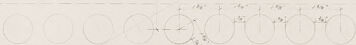
This image appears to be a reproduction of an architectural drawing or blueprint. It shows a technical drawing with various elevations and sections of a building design, including a floor plan at the top and cross-section detail at the bottom. Annotations and measurements are provided to guide construction or provide specifics about the building elements and materials, such as "ELEV. MASONITE" indicated on the drawing. The drawing typically would be used by architects, engineers, and builders to understand how to construct the building features shown. The text is too small to read in detail, but there are also labels, notes, and dimensions that assist in interpreting the drawings. On the bottom right-hand corner, there is a title block that typically contains information such as the name of the project, the scale of the drawing, the date of creation, and the names of the people or firms involved in the design. In this case, the name of the architectural firm listed is "Ritchey & Mitchell" located in Pittsburgh, Pennsylvania, and the work appears to be associated with "Walter Gropius & Marcel Breuer," well-known modernist architects.
Created by gpt-4o-2024-05-13 on 2025-03-05
The image displays an architectural drawing or blueprint, specifically a detailed section and elevation plan. The drawing, primarily done in pencil, appears to exhibit dimensions, materials, and construction details for a specific part of a building or structure. Key elements of the drawing include: 1. Circular features: Several circles are shown in a grid layout, possibly representing holes or openings. 2. Text annotations: Various sections are labeled with notations, such as "EX. ELEV. MASONITE FRONTS," "F.F. BURNS," and specifications of materials used. 3. Dimensions: Measurement lines and numerical values indicating the dimensions of the structure. 4. Cross-sections: Detailed cross-sectional views showing the internal structure and materials. 5. Professional information: The bottom right corner includes details of the architectural firms involved - "RITCHEY & MITCHELL REGISTERED ARCHITECTS PITTSBURGH, PENNA" and "WALTER GROPIUS & MARCEL BREUER ASSOCIATE ARCHITECTS, CAMBRIDGE, MASS." Additionally, there's a small note indicating revisions and a date, "JAN 14 1937." The drawing appears to be a professional architectural plan, likely used in the construction or renovation of a building, providing specific instructions and dimensions for builders and contractors.
Anthropic Claude
Created by claude-3-haiku-20240307 on 2024-12-29
This image appears to be an architectural or engineering blueprint or technical drawing. It contains various geometric shapes, dimensions, and labels that suggest it is a detailed design or plan for some kind of structure or system. The image does not contain any human faces or identifiable individuals, so I will not mention or describe any such elements. Instead, I will focus on the technical details and layout presented in the drawing.
Created by claude-3-5-sonnet-20241022 on 2024-12-29
This appears to be an architectural drawing or blueprint showing construction details. The image shows different views and cross-sections of what looks like a masonite installation or construction element. The drawing includes a plan view with circular patterns arranged in a grid, as well as elevation views showing structural details. There are measurements and annotations throughout the drawing, and it appears to be done in a professional architectural drafting style. The drawing has a title block in the bottom right corner indicating it was created by architectural firms. The overall drawing is done in a light, faded style typical of vintage architectural blueprints or drawings.
Meta Llama
Created by us.meta.llama3-2-11b-instruct-v1:0 on 2025-03-12
The image presents a detailed architectural drawing, showcasing a building's design and layout. The drawing is rendered in black and white, with various lines, shapes, and text used to convey the information. * **Title and Credits** * The title of the drawing is not explicitly stated, but it appears to be a section of a larger plan. * The credits at the bottom of the page read "RITCHEY & MITCHELL ASSOCIATED ARCHITECTS PITTSBURGH, PENNA." and "walter gropius & marcel breuer associated architects cambridge, mass." * **Drawing Details** * The drawing features a series of lines, shapes, and text that outline the building's design and layout. * The drawing includes various symbols, such as circles, squares, and triangles, which may represent different elements of the building, such as windows, doors, or columns. * The text on the drawing appears to be handwritten and includes notes, measurements, and other annotations. * **Scale and Dimensions** * The drawing includes a scale bar at the bottom, which indicates that the drawing is to a specific scale (1/4 inch = 1 foot). * The drawing also includes dimensions and measurements, which provide further details about the building's design and layout. * **Overall Impression** * The drawing appears to be a detailed and accurate representation of the building's design and layout. * The use of various symbols, text, and annotations suggests that the drawing is intended for a specific purpose, such as construction or renovation. In summary, the image presents a detailed architectural drawing that showcases a building's design and layout. The drawing includes various symbols, text, and annotations, and is accompanied by a scale bar and dimensions. The overall impression is one of accuracy and attention to detail, suggesting that the drawing is intended for a specific purpose, such as construction or renovation.
Created by us.meta.llama3-2-90b-instruct-v1:0 on 2025-03-12
This image is a technical drawing of a building's architecture, specifically focusing on the masonry and elevation details. The drawing is presented in black ink on a white background, with various symbols, measurements, and annotations scattered throughout. In the bottom-right corner, a small box contains the names "Walter Gropius & Marcel Breuer" and "Ritchey & Mitchell," along with their respective addresses in Cambridge, Mass., and Pittsburgh, Penna. This suggests that the drawing was created by or for one of these architectural firms. The drawing itself appears to be a detailed plan for a building's exterior, including the placement of windows, doors, and other features. The use of technical symbols and measurements indicates that this is a professional-grade architectural drawing, likely used for construction or planning purposes. Overall, this image provides a glimpse into the meticulous process of architectural design and planning, highlighting the attention to detail and precision required to bring a building project to life.
Amazon Nova
Created by amazon.nova-lite-v1:0 on 2025-01-11
The image is a technical drawing, likely from an architectural or engineering project. It features a layout plan with various annotations and measurements. The drawing includes a series of circles, possibly representing windows or openings, arranged in a grid-like pattern. The text "F.S. ELEV. MASONITE FRONTS" is visible, indicating that this might be a floor plan or elevation view of a building's facade. The drawing also includes detailed notes and dimensions, suggesting it is a working draft or blueprint. The image is monochromatic, predominantly white with black lines and text.
Created by amazon.nova-pro-v1:0 on 2025-01-11
The image is a detailed architectural blueprint, likely for a residential or commercial building. It is a large, white sheet of paper with various sections and annotations. The top section contains a grid of circles, possibly representing a floor plan or a specific design element. Below this, there are more detailed drawings of what appears to be a building's elevation and cross-section. The drawings are annotated with measurements, notes, and labels such as "F.S. ELEV. MASONITE FRONTS," "F.S. ELEV. MASONITE (COURTIER SIDE)," and "F.S. PLAN (COURTIER ENCLOSED)." There are also references to "RITCHEY & MITCHELL" and "PITTSBURGH, PENNA," suggesting the architects or the location of the project. The bottom right corner has a stamp or signature, indicating the document's official status.
Text analysis
Amazon