Machine Generated Data
Tags
Color Analysis
Categories
Imagga
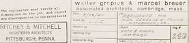
| text visuals | 100% | |
Captions
Microsoft
created on 2018-03-22
| a close up of text on a white background | 81.9% | |
| a close up of text on a black background | 76.6% | |
| a close up of text on a white surface | 76.5% | |
OpenAI GPT
Created by gpt-4o-2024-05-13 on 2025-03-07
The image is an architectural blueprint likely created by the firm Wurster, Gropius & Marcel Breuer. The blueprint consists of a series of detailed technical drawings and schematics for a building project. Key elements include: 1. **Front Elevation**: This is a straight-on view of the building or structure from the front, showing the facade and detailing its vertical dimensions. 2. **Sections A-A and B-B**: These drawings cut through the structure, showing internal details as if the building was sliced along the lines A-A and B-B. These sections provide a view of the construction elements that are not visible from the exterior drawings. 3. **Plan (with case above removed)**: This is a horizontal cross-sectional view, typically taken at a specific height, like the floor plan. It shows the arrangement of spaces and relationships between them from above, outlining the floor layout. 4. **Details**: Smaller, zoomed-in diagrams that depict specific construction details or joints, like the one labeled "Detail Below Stool." These sections emphasize particular architectural elements and construction techniques. Text annotations and dimension lines are included throughout the blueprint to provide precise measurements and construction notes. The blueprint is marked by the architectural firm Ritchey & Mitchell, Pittsburgh, Penna., suggesting they have contributed to the design or construction process. The title block also notes the involvement of architects Walter Gropius and Marcel Breuer, associating the drawing with these prominent figures in modern architecture. Revisions and additional notes might also be present to indicate changes or important information for the builders.
Created by gpt-4 on 2025-03-07
The image depicts an architectural drawing or blueprint with several views of a design. The drawing includes detailed plans and sections of an object, which appears to be a piece of furniture—possibly a desk or table. There are annotations and measurements indicating dimensions and construction techniques. On the drawing, one can identify different sections labeled as "FRONT ELEVATION," "SECTION 'A-A'," "SECTION 'B-B'," and "PLAN (WITH CASE BELOW REMOVED)." These labels suggest different perspectives of the item being represented: the front view, cross-sectional views, and a view of the plan without a part of the structure for clarity. The lower right of the image contains text, but the font is small and not entirely legible in this view. However, the text likely includes the names of the architects or designers, the title or purpose of the plan, and possibly the date, location, or project details. It is clear that this is a professional technical drawing, and it reflects precision and attention to detail appropriate to architectural or industrial design work. The text at the bottom right corner has names "Walter Gropius & Marcel Breuer" and "Architects" indicating the creators of the design, and further text "The Architects Collaborative, Cambridge, Mass." suggests the associated architectural firm. Below this, the names "RICHTER & MITCHELL" alongside "PITTSBURGH, PENNA", likely refer to additional associated parties or the location related to the project.
Anthropic Claude
Created by claude-3-haiku-20240307 on 2024-12-30
This image appears to be a technical drawing or blueprint, possibly for some kind of architectural or engineering project. It contains detailed plans and measurements for various components or sections, indicating it is a detailed technical diagram rather than an artistic or illustrative image. The drawing appears to be focused on structural or design elements, without depicting any human figures or other recognizable objects.
Created by claude-3-opus-20240229 on 2024-12-30
The image shows architectural plans and diagrams drawn by hand on a grid paper background. The plans depict floor layouts, elevations, and section views of what appears to be a residential or commercial building. Dimensions and annotations are included to specify wall thicknesses, room sizes, and other construction details. The plans use thin lines and text labels to communicate the architectural design intent. A title block in the bottom right provides project information, but the exact details are not clearly legible in this image resolution. Overall, it is a detailed set of manually drafted architectural drawings following standard conventions.
Created by claude-3-5-sonnet-20241022 on 2024-12-30
This is an architectural or engineering drawing showing various technical details and specifications. The drawing includes multiple views: 1. A front elevation view 2. Section views labeled "A-A" and "B-B" 3. A plan view (noted as "WITH CASE SIDES REMOVED") 4. A small detail of what appears to be "RESIN STOCK" The drawings are done in a professional drafting style with dimensions and annotations throughout. The title block in the bottom right corner indicates this is from a firm in Pittsburgh, Pennsylvania. The drawing appears to be for some kind of case or cabinet design, with precise measurements and construction details shown from multiple angles. The scale noted on some views is 1/2"=1'-0". The drawing is rendered in black and white with clear, crisp lines typical of architectural/engineering documentation.
Meta Llama
Created by us.meta.llama3-2-11b-instruct-v1:0 on 2025-03-14
The image depicts a technical drawing of a building, showcasing its front elevation, section, and bed stock. The drawing is rendered in pencil on white paper and includes handwritten notes and labels. **Key Features:** * **Front Elevation:** The top portion of the drawing displays the front elevation of the building, featuring a detailed outline of the structure's facade. * **Section:** The middle section of the drawing illustrates a cross-section of the building, providing insight into its internal layout and design. * **Bed Stock:** The bottom portion of the drawing focuses on the bed stock, which appears to be a storage area or room within the building. * **Handwritten Notes and Labels:** Throughout the drawing, handwritten notes and labels provide additional information about the building's design and features. **Context:** The drawing is likely a part of a larger architectural plan or design document, created by Walter Gropius and Marcel Breuer, associated architects from Cambridge, Massachusetts. The drawing is dated 1943 and bears the notation "Ritchey & Mitchell Associated Architects Pittsburgh, Penna." in the bottom-right corner. **Purpose:** The purpose of this drawing is to provide a detailed and accurate representation of the building's design, allowing architects, engineers, and contractors to understand and execute the project. The drawing serves as a crucial tool for communication and collaboration among stakeholders involved in the construction process.
Created by us.meta.llama3-2-90b-instruct-v1:0 on 2025-03-14
The image presents a collection of architectural drawings, likely created for a building or structure. The drawings are rendered in black ink on a white background, with various sections and elevations depicted. **Key Features:** * **Multiple Drawings:** The image contains several drawings, each showcasing different aspects of the design. * **Black Ink on White Background:** The drawings are executed in black ink on a white background, providing clear visibility and contrast. * **Various Sections and Elevations:** The drawings depict various sections and elevations of the structure, offering a comprehensive view of the design. **Overall Impression:** The image appears to be a set of architectural drawings, possibly created for a specific project or proposal. The level of detail and precision suggests that these drawings were intended for professional use, such as in the construction or renovation of a building.
Amazon Nova
Created by amazon.nova-pro-v1:0 on 2025-01-11
The image is a technical drawing of a building's floor plan, specifically focusing on the front elevation and sections A-A and B-B. The drawing is labeled "PLAN (WITH CASE ABOVE REMOVED)" and includes a detailed layout of the building's interior and exterior features. The drawing includes dimensions, annotations, and notes related to the construction and design of the building. The drawing is in black and white, with a grid overlay to help with precise measurements and alignment. The drawing is likely used by architects, engineers, and construction professionals to plan and execute the building's construction.
Created by amazon.nova-lite-v1:0 on 2025-01-11
This image is a technical drawing or blueprint of a structure, possibly a building or a part of a building. The drawing is divided into four sections, each with a different title and scale. The top left section is titled "FRONT ELEVATION" and shows a front view of the structure with dimensions and measurements. The top right section is titled "SECTION A-A" and shows a cross-sectional view of the structure with dimensions and measurements. The bottom left section is titled "PLAN (WITH CASE ABOVE REMOVED)" and shows a plan view of the structure with dimensions and measurements. The bottom right section is titled "F.S. PLAN BELOW STOCK" and shows a plan view of the structure below a certain level, with dimensions and measurements. The drawing is signed by "Walter Gropius & Marcel Breuer" and "Ritchey & Mitchell," indicating the architects and engineers involved in the design and construction of the structure.
Text analysis
Amazon