Machine Generated Data
Tags
Color Analysis
Feature analysis
Amazon
| Document | 71.7% | |
Categories
Imagga
| text visuals | 99.9% | |
| paintings art | 0.1% | |
Captions
Microsoft
created on 2018-03-22
| a close up of text on a white background | 67.5% | |
| a close up of text on a white surface | 65.3% | |
| a close up of text on a black background | 59.7% | |
OpenAI GPT
Created by gpt-4 on 2025-03-06
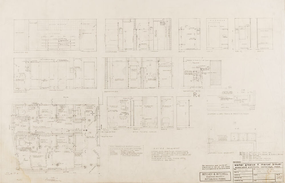
This is an architectural drawing or blueprint. The image shows a detailed plan view of a building at the bottom, with various rooms and sections labeled with dimensions and notes. Above the plan view, there are elevation drawings detailing the facade of the building from different angles (labeled as "Elevation A-A," "Elevation B-B," and so on). Notes and measurements on the elevations indicate sizes and distances between elements of the building's design. In the bottom right corner, there appear to be some stamps and text which indicate the architects, Walter Gropius & Marcel Breuer, and their associated address in Cambridge, Massachusetts. The architecture firm responsible for drafting the plan is Ritchey & Mitchell, located in Pittsburgh, Pennsylvania. The drawing has a dated appearance, suggesting it may be from the mid-20th century, which is consistent with the active period of the named architects who were prominent modernist architects of that time.
Created by gpt-4o-2024-05-13 on 2025-03-06
This image is a detailed architectural blueprint drawing or construction plan. The blueprint appears to show various elevations, plans, and sections for a building or a complex of structures. Key features of the blueprint include: - **Multiple Elevations** (labeled as Elevation AB, Elevation BC, and so forth): These are vertical orthographic projections that show the vertical faces of the building, highlighting how the exterior will look from different angles. - **Sections and Details**: Detailed cross-sectional drawings that offer insight into the internal arrangement and structure. - **Plan View**: Includes a floor plan which is a horizontal cut through the building, detailing the layout including rooms, corridors, fixtures, and furniture placement. - **Annotations and Labels**: Various parts of the blueprints contain text annotations that indicate materials, dimensions, and specific construction notes. - **Title Block**: In the bottom right corner, the title block contains important information about the project, including the names of the architects (Walter Gropius & Marcel Breuer) and the architecture firm (Ritchey & Mitchell), the location (Pittsburgh, Penna), and other relevant data such as project revision notes and dates. - **Scale and Measurements**: The blueprint includes scales and measurements that are crucial for translating the drawing into real-world dimensions for construction purposes. The drawing is detailed and technical, filled with precise lines and measurements indicative of professional architectural documentation.
Anthropic Claude
Created by claude-3-haiku-20240307 on 2024-12-30
This image appears to be an architectural blueprint or technical drawing. It contains numerous detailed diagrams, measurements, and annotations that seem to depict various structural and design elements. The drawing style and the technical nature of the content suggest this is likely a set of construction plans or schematics for a building or structure. The overall layout and organization of the different sections and views indicates this is a comprehensive set of design specifications, though without further context I cannot determine the specific purpose or nature of the structure depicted.
Created by claude-3-5-sonnet-20241022 on 2024-12-30
This appears to be an architectural floor plan or blueprint drawing. The image shows multiple detailed interior layouts and elevations, with various rooms and spaces marked out. The drawing is done in a technical style typical of architectural drawings, with thin lines showing walls, doors, and other building elements. The drawing contains several different views or sections arranged on a single sheet, with the largest floor plan appearing in the bottom portion of the image. There are what appear to be elevation drawings in the upper and middle portions. The document has a title block in the lower right corner, which is typical of professional architectural drawings. The overall tone of the image is light, with the drawings appearing in black or dark lines on a light background.
Meta Llama
Created by us.meta.llama3-2-11b-instruct-v1:0 on 2025-03-12
The image presents a detailed architectural floor plan, comprising multiple rooms and spaces. The plan is rendered in black ink on a white background, with various rooms and spaces depicted in a two-dimensional format. **Key Features:** * **Room Layout:** The floor plan showcases a range of rooms, including living areas, bedrooms, bathrooms, and kitchens. Each room is carefully labeled and dimensioned, providing a clear understanding of the space's layout and proportions. * **Dimensions:** The plan includes precise measurements for each room, allowing architects, builders, and designers to accurately scale and replicate the design. * **Labels and Annotations:** Throughout the plan, various labels and annotations are used to identify different features, such as doors, windows, and electrical outlets. These labels provide valuable context and help to clarify the purpose of each room or space. * **Scale:** The plan is drawn to scale, ensuring that the dimensions and proportions of each room are accurately represented. This allows for precise planning and execution of the design. * **Architectural Style:** The floor plan appears to be from an older architectural style, with features such as ornate moldings, intricate details, and classic proportions. This suggests that the building may have been designed in the early 20th century or earlier. **Conclusion:** The image provides a detailed and informative architectural floor plan, showcasing a range of rooms and spaces with precise measurements and labels. The plan's classic style and attention to detail suggest that it may be from an older building, and its value lies in its ability to provide a clear understanding of the space's layout and proportions.
Created by us.meta.llama3-2-90b-instruct-v1:0 on 2025-03-12
This image is a technical drawing of the floor plan for a building, likely created by an architect or engineer. The drawing is rendered in black ink on a white background and features a series of rectangular boxes, each representing a room or space within the building. The drawing includes various symbols, labels, and notations that provide additional information about the design. These may include measurements, materials, and other details relevant to the construction process. In the bottom-right corner of the image, there is a small box with text that appears to be the signature or stamp of the architect or engineer who created the drawing. This box also contains other text, including the name of the architectural firm, the location of the project, and the date of the drawing. Overall, this image provides a detailed and precise representation of the building's layout and design, which would be useful for construction purposes.
Amazon Nova
Created by amazon.nova-lite-v1:0 on 2025-01-12
The image appears to be an architectural floor plan or blueprint for a residential building. The image shows various sections and layouts of the building, including floor plans, elevations, and sections. The floor plans depict the layout of rooms, doors, windows, and other architectural features. The elevations show the exterior views of the building from different angles, while the sections provide a vertical cross-section of the building, showing the internal structure and layout. The image also includes notes and labels that provide additional information about the building's design and construction. The overall appearance of the image suggests that it is a technical drawing or blueprint created by architects or engineers for the purpose of designing and constructing a residential building.
Created by amazon.nova-pro-v1:0 on 2025-01-12
The image is a technical drawing that appears to be a floor plan of a building. It is divided into multiple sections, each representing different parts of the building. The drawing includes measurements and annotations, indicating the dimensions and layout of the rooms. The text "Walter Gropius & Marcel Breuer" is visible at the bottom right corner, suggesting that these individuals were involved in the design or architecture of the building. The overall appearance of the drawing suggests that it is a professional architectural plan used for construction or renovation purposes.
Text analysis
Amazon