Machine Generated Data
Tags
Color Analysis
Feature analysis
Amazon
Clarifai

Clarifai
| Whiteboard | 44.8% | |
Categories
Imagga
created on 2018-03-22
| text visuals | 100% | |
Captions
Microsoft
created by unknown on 2018-03-22
| a close up of a map | 89% | |
| a map with text | 83.2% | |
| close up of a map | 83.1% | |
Clarifai
No captions written
Salesforce
Created by general-english-image-caption-blip on 2025-05-11
a photograph of a drawing of a plan for a house
Created by general-english-image-caption-blip-2 on 2025-06-28
a drawing of a building with plans and drawings
OpenAI GPT
Created by gpt-4 on 2025-03-06
This image depicts a set of architectural drawings or blueprints. The drawings include various views and details of a structure with annotations and measurements.
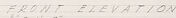
In the top left, there is a portion labeled "SIDE WALL BEARING." Below that, on the left side of the page, is a larger drawing labeled "FRONT ELEVATION" displaying the front view of a design with notations, such as "BRICK SECTION" and "STONE SECTION." To the right of this drawing is a section marked "PLAN" indicating a top-down view of a corner section of the design.
On the top right, there's another labeled "SIDE WALL BEARING." Below that, another section called "END ELEVATION" shows the end view of the structure with similar detailed notations. To the right of this is another detailed section labeled "SECTION A-A," presumably a cut-through to show the interior structure of a specific part.
Throughout the image, you can see various technical notes, dimensions, and material indications such as brick, stone, and wood. The drawings are meticulously detailed and seem to communicate the specific construction details of a building.
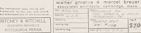
In the bottom right corner, you can see some text indicating the names Walter Gropius & Marcel Breuer, associated architects, suggesting that these influential figures may be responsible for the design. There's also a mention of "Ritchie & Mitchell," located in Pittsburgh, PA, possibly the draftsman or architect firm that produced or copied the drawings. The date "2-28-36" could indicate that these plans were created or revised on February 28, 1936.
Created by gpt-4o-2024-05-13 on 2025-03-06
The image is an architectural technical drawing. The drawing includes multiple views and sections of a building or a structure. Here are the key features and labels that can be observed:
Views and Sections:
- Front Elevation: Depicts the front view of the structure.
- End Elevation: Provides a view from the side or end of the structure.
- Plan: A top view (layout) showing the arrangement and dimensions.
- Section A-A: A cross-sectional view, providing insights into the internal structure along a specific line.
Labels and Annotations:
- Various measurements and construction details are labeled, including materials used, dimensions, and specific instructions for construction (e.g., brick, laminated plywood, etc.).
- Specific call-outs to construction notes and drawing details, such as "Full Size - This Corner" and various sections that are partially detailed for clarity.
Drawings:
- Details of window or wall sections are meticulously outlined with notations describing materials, dimensions, and assembly methods.
- The drawing provides comprehensive assembly details and guidance for construction.
Title Block:
- The bottom right corner includes essential information like the architects' names and firms involved, which are "Walter Gropius & Marcel Breuer" and "Ritchey & Mitchell".
- It also includes project details such as project numbers, dates, and revision information.
This technical drawing serves as a precise guide for builders and architects to understand the design and construction details of the structure being depicted.
Anthropic Claude
Created by us.anthropic.claude-3-5-sonnet-20241022-v2:0 on 2025-06-24
This image appears to be an architectural drawing or blueprint. It shows both elevation and section views (marked as "SECTION A-A") of what seems to be a building design. The drawing includes detailed technical specifications, measurements, and construction notes. The drawing is primarily in black and white with fine lines and text annotations throughout. At the bottom of the drawing, there appears to be a title block with what looks like project information and architect/designer details. The drawing style is typical of professional architectural documentation used for construction purposes. The level of detail suggests this is a working document rather than a conceptual sketch.
Created by claude-3-haiku-20240307 on 2024-12-30
This image appears to be a technical drawing or architectural blueprint. It shows detailed front and side elevations, as well as a section view, of what looks like a structure or building. The drawing contains various annotations, measurements, and technical details, indicating that this is an engineering or construction-related document rather than an artistic representation. Without being able to identify any individuals, the image focuses on the structural and design elements of the subject matter.
Created by claude-3-opus-20240229 on 2024-12-30
The image shows an architectural blueprint or plan view drawing. It depicts the layout and dimensions of what appears to be a building section or floor plan. The drawing includes various rectangular spaces connected by lines, likely representing rooms, hallways or other architectural elements. Measurements and annotations are handwritten throughout the blueprint providing sizing and other technical details. In the bottom right corner there is a title block with project information filled out by hand. The blueprint has an aged, textured appearance, suggesting it may be an older, historical architectural drawing.
Created by claude-3-5-sonnet-20241022 on 2024-12-30
This is an architectural technical drawing or blueprint showing various elevations, a plan view, and a section detail. The drawing appears to be for some kind of interior built-in or millwork element, likely for the Ritchey & Mitchell project in Pittsburgh, PA, as noted in the title block. The drawing includes front and side elevations, a plan view showing spatial layout, and a detailed section marked as "Section A-A" which shows construction specifics. The drawing is done in a professional architectural style with dimensions, notes, and proper scaling indicated. The lines are precise and the drawing includes various technical specifications and construction notes. It's rendered in a typical architectural drawing style with light pencil or ink lines on what appears to be drafting paper.
Meta Llama
Created by us.meta.llama3-2-11b-instruct-v1:0 on 2025-03-12
The image is a technical drawing of a building's floor plan and elevation, with handwritten notes and measurements. The drawing appears to be a detailed architectural plan for a building, likely created by an architect or engineer.
- Floor Plan:
- The floor plan is drawn in a rectangular shape, with various rooms and spaces labeled.
- The rooms are represented by rectangles, with doors and windows indicated by lines and symbols.
- There are several notes and annotations throughout the floor plan, including measurements, labels, and arrows.
- Elevation:
- The elevation is drawn in a similar style to the floor plan, with a rectangular shape representing the building's exterior.
- The elevation includes details such as windows, doors, and other architectural features.
- There are also notes and annotations on the elevation, including measurements and labels.
- Handwritten Notes:
- The drawing includes several handwritten notes and annotations, which appear to be written in pencil.
- The notes provide additional information about the building's design and construction, including measurements, materials, and techniques.
- Some of the notes are illegible, but others appear to be important details about the building's layout and features.
- Measurements:
- The drawing includes several measurements, which are written in both inches and feet.
- The measurements appear to be precise, with decimal points and fractions used to indicate exact dimensions.
- The measurements are likely used to ensure that the building is constructed accurately and to scale.
- Labels and Symbols:
- The drawing includes several labels and symbols, which are used to identify different parts of the building.
- The labels and symbols appear to be standardized, with each one representing a specific feature or element of the building.
- The labels and symbols are likely used to facilitate communication between architects, engineers, and contractors during the construction process.
Overall, the image is a detailed and technical drawing of a building's floor plan and elevation, with handwritten notes and measurements. The drawing provides a comprehensive overview of the building's design and construction, and is likely used as a reference for architects, engineers, and contractors.
Created by us.meta.llama3-2-90b-instruct-v1:0 on 2025-03-12
This image depicts a detailed architectural blueprint, showcasing the intricate design of a building's layout. The blueprint is divided into three main sections: a front elevation, an end elevation, and a plan view. Each section provides a unique perspective on the building's structure, with precise measurements and annotations that offer insight into the architect's vision.
The front elevation section presents a two-dimensional representation of the building's facade, highlighting the arrangement of windows, doors, and other exterior features. The end elevation section offers a similar perspective from the side, while the plan view provides a bird's-eye view of the building's floor plan.
The blueprint also includes various symbols, abbreviations, and notes that provide additional context and information about the design. These elements are likely intended for use by architects, engineers, and contractors who will be responsible for bringing the design to life.
Overall, this image provides a fascinating glimpse into the world of architecture and design, showcasing the attention to detail and precision that goes into creating a functional and aesthetically pleasing building.
Amazon Nova
Created by amazon.nova-lite-v1:0 on 2025-01-12
This image is a technical architectural drawing, likely from a construction or renovation project. The drawing is divided into several sections, including a front elevation, an end elevation, and a plan view. The drawing features various lines, dimensions, and annotations that indicate the dimensions, materials, and structural details of the project. The drawing is labeled with the names of the architects, Walter Gropius and Marcel Breuer, and the location of the project, Pittsburgh, Pennsylvania. The drawing appears to be a detailed and precise representation of the project's design and specifications.
Created by amazon.nova-pro-v1:0 on 2025-01-12
The image is a detailed architectural blueprint, specifically a plan view of a building's corner section. The blueprint is laid out on a white background with black and red ink lines and annotations. The plan view is a top-down perspective that shows the layout and dimensions of the building's corner. The blueprint includes various sections, such as the front elevation, end elevation, and partial sections. The annotations provide information about the materials, dimensions, and construction details of the building. The blueprint also includes a legend that explains the symbols and abbreviations used in the drawing. Overall, the blueprint provides a comprehensive overview of the building's corner section, including its layout, dimensions, and construction details.
Google Gemini
Created by gemini-2.0-flash on 2025-05-12
Here is a description of the image:
The image appears to be an architectural drawing or blueprint, likely for a construction or renovation project. It includes several detailed diagrams and annotations with fine lines and handwritten notes.
The drawing is organized into different sections, each labeled with a title and scale. There is a "FRONT ELEVATION," "END ELEVATION," "PLAN," "PARTIAL SECTION B-B," "PARTIAL SECTION C-C," and "SECTION A-A." Each section provides a different view or cut of the structure, showing dimensions and materials.
The notes and annotations provide additional information and instructions, such as the types of materials to be used, how joints should be constructed, and specific requirements for finishing surfaces.
The drawing is credited to "Walter Gropius & Marcel Breuer, associated architects, Cambridge, Mass," and "Richey & Mitchell, Registered Architects, Pittsburgh, Penna."
The overall impression is that this is a technical document used for guiding construction or renovation work, requiring careful attention to detail and adherence to specifications.
Created by gemini-2.0-flash-lite on 2025-05-12
This is a blueprint or architectural drawing. It appears to be for a building or part of a building. The drawing contains various views and sections:
- Front Elevation: This shows the building's exterior from the front.
- End Elevation: This depicts the building's exterior from one of its sides.
- Partial Sections: "Section B-B" and "Section C-C" provide views of specific details of the building, showing the internal structure of walls and features.
- Section A-A: Another cross-section, likely providing details on construction methods.
- Plan: A top-down view of a small corner, probably the floor plan.
- Full Size - This Corner: Gives the construction detail, possibly of a corner joint.
The drawing is highly detailed, with annotations, dimensions, and labels throughout. It includes notes and specifications. The title at the bottom indicates the architects are Walter Gropius and Marcel Breuer, and the firm is Ritchey & Mitchell. The location is noted as Pittsburgh, Pennsylvania. This suggests the blueprint is for a design by these well-known architects.
Mistral Pixtral
Created by us.mistral.pixtral-large-2502-v1:0 on 2025-05-30
The image is an architectural drawing that provides detailed plans for a building. Here's a breakdown of the different sections shown:
Title Block Section:
- Located at the bottom right corner, it includes information about the project, such as the names of the architects (Walter Gropius and Marcel Breuer), the architectural firm (Ritchley & Mitchell), and the project's location (Lincoln, Massachusetts).
- It also contains a drawing number (270), scale (1/2" = 1'-0"), and date (July 1938).
Front Elevation:
- This section shows the front view of the building. It includes details of the facade, such as windows, doors, and structural elements.
- There are notes indicating materials and finishes, such as "black asphalt base" and "red cedar."
End Elevation:
- This section shows the side view of the building. It provides details similar to the front elevation but from a different perspective.
- It includes structural elements and notes on materials.
Section A-A:
- This is a cross-sectional view of the building, providing a vertical slice through the structure.
- It shows internal elements such as walls, floors, and roof structure.
- Detailed notes and dimensions are included to specify construction details.
Detail Drawings:
- There are smaller detailed drawings within the main sections, focusing on specific elements such as corners and joints.
- These details provide more precise information on how certain parts of the structure should be constructed.
Notes:
- The drawing includes several notes providing additional instructions and specifications for the construction.
- These notes are crucial for ensuring that the building is constructed according to the architect's intentions.
Overall, this architectural drawing is a comprehensive plan that provides all necessary details for constructing the building, including dimensions, materials, and specific construction techniques.
Qwen
Created by Qwen/Qwen2.5-VL-7B-Instruct on 2025-07-20
The image is a technical drawing or architectural plan, likely detailing the construction or design of a specific structure or section of a building. It includes multiple views and sections, such as front elevation, end elevation, and a section labeled "Section A-A." The drawing is quite detailed, with annotations and measurements indicating the materials and dimensions of the structure. Terms like "tile wall," "loose leaf construction," and "black linoleum base" suggest the use of specific building materials. The plan also includes dimensions and labels for various parts of the structure, such as "2" x 1" o." This type of drawing is commonly used in construction and architecture to provide a comprehensive understanding of the building's design and construction requirements. The bottom of the document includes a note from "Walter Gropius & Marcel Breuer," indicating that the architects responsible for the design are Walter Gropius and Marcel Breuer, who were prominent figures in the Bauhaus school of design.
Created by Qwen/Qwen2.5-VL-72B-Instruct on 2025-07-20
This image is an architectural drawing or blueprint. It contains various views and sections of a structure, including front elevation, end elevation, and a section labeled "SECTION A-A." The drawing includes detailed annotations and measurements, indicating the dimensions and specifications of the structure. The bottom right corner includes the names "Walter gropius & marcel breuer" and "Ritchey & Mitchell," likely referring to the architects and possibly the engineering firm involved in the project. The drawing also includes a plan view and a note section with additional details and instructions. The style and annotations suggest it is a technical drawing used for construction purposes.
Text analysis
Amazon