Machine Generated Data
Tags
Color Analysis
Categories
Imagga
| text visuals | 99.7% | |
| paintings art | 0.2% | |
Captions
Microsoft
created on 2018-03-22
| a close up of text on a white surface | 57.9% | |
| a close up of text on a white background | 57.5% | |
| close up of text on a white surface | 52.3% | |
OpenAI GPT
Created by gpt-4 on 2025-03-07
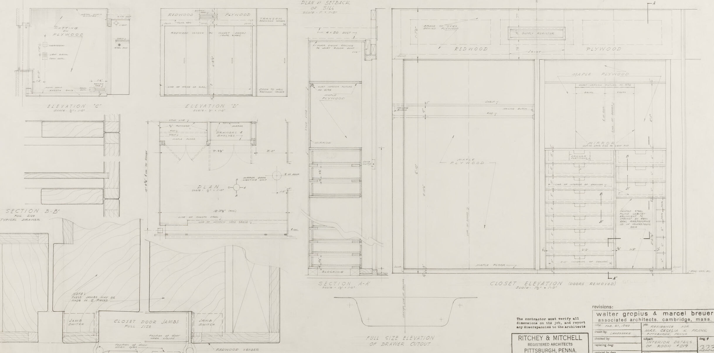
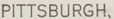
This is a technical architectural drawing or blueprint, featuring multiple views and sections of what appears to be some details of a building, possibly specific elements like closets or storage units. The drawing includes various elevations and sections, each meticulously annotated with dimensions, materials, and construction notes. Different parts of the designs specify the use of plywood and redwood, suggesting the structure or furnishings this plan is for. There are numerous labels indicating different views such as "Elevation," "Plan of Closets," "Section," and "Closet Door Jamb." The precision of the lines and the crisp labeling indicate professional drafting work. In the bottom right corner, there is some text noting revisions made by two individuals: Walter Gropius and Marcel Breuer, both of whom are notable figures in the world of architecture. Additional information includes another entity, "Ritchie & Mitchell," located in Pittsburgh, PA, along with a date which is not fully visible. The presence of renowned architects like Gropius and Breuer suggest that this drawing could be related to an important architectural project or may have historical significance.
Created by gpt-4o-2024-05-13 on 2025-03-07
This image shows detailed architectural plans or blueprints for a residential project involving closet designs. The drawings are meticulously labeled with measurements, material specifications, sectional views, and elevations. On the right-hand side, the plans provide a header that references revisions involving architects Walter Gropius and Marcel Breuer, noted figures in modern architecture, in collaboration with Ritchey & Mitchell Architects from Pittsburgh, Pennsylvania. This information is noted in the bottom right corner of the sheet. The image displays multiple views including: - Elevations of the closets, detailing both plywood and redwood materials. - Plans of closet arrangements indicating dimensions and structural details. - Cross-sections illustrating construction details, and - Enlarged sections and details showing specific parts of the closet construction, such as doors, jabs evolution, and typical details. These technical diagrams are drawn with precision, indicating a detailed guide for the construction and implementation of closet spaces within the residential architecture project.
Anthropic Claude
Created by claude-3-haiku-20240307 on 2024-12-31
This image appears to be an architectural drawing or blueprint. It contains various detailed technical drawings, elevations, and plans for what seems to be a piece of furniture or cabinetry. The drawings include precise measurements, annotations, and specifications, suggesting this is a technical design document used for the construction or manufacturing of this item. There are no human faces or identities visible in this image.
Created by claude-3-opus-20240229 on 2024-12-31
The image shows detailed architectural drawings and plans for what appears to be kitchen and bathroom cabinetry. It includes precise measurements, elevations showing the front and side views of the cabinets, and sectional views revealing the interior construction. The plans specify details like shelf placement, drawer sizes, and the overall dimensions of each cabinet unit. A title block in the bottom right corner identifies this as drawings for "Ritchey & Mitchell", likely the client or project name, by Walter Grogins & Marcel Breuer Associates, who seem to be the architectural firm. The meticulous drafting and labeling suggests these are professional construction documents used to guide the fabrication and installation of custom cabinetry.
Created by claude-3-5-sonnet-20241022 on 2024-12-31
This appears to be an architectural drawing or blueprint showing detailed closet and storage designs. The document includes multiple views - elevations, sections, and plans - of what seems to be built-in closet configurations. The drawings are technical in nature, with precise measurements and annotations. At the bottom of the sheet, there's a title block indicating this was created by Walter Gropius & Marcel Breuer Associated Architects from Cambridge, Massachusetts, for Ritchey & Mitchell in Pittsburgh, Pennsylvania. The plans show various storage solutions including shelving units, hanging spaces, and drawer configurations. The drawing style is characteristic of mid-century architectural documentation, with clean lines and detailed specifications.
Meta Llama
Created by us.meta.llama3-2-11b-instruct-v1:0 on 2025-03-17
The image is a detailed architectural blueprint, showcasing the floor plan and elevations of a building. The blueprint is drawn in pencil on white paper and features a range of architectural elements, including walls, doors, windows, and closets. **Key Features:** * **Floor Plan:** The floor plan is divided into several sections, each representing a different room or area of the building. The rooms are labeled with their corresponding names, such as "Living Room," "Kitchen," and "Bedroom." * **Elevations:** The elevations are depicted in a series of drawings that show the exterior of the building from different angles. These drawings provide a detailed view of the building's facade, including the placement of windows, doors, and other architectural features. * **Architectural Elements:** The blueprint includes a variety of architectural elements, such as walls, doors, windows, and closets. These elements are carefully labeled and dimensioned, providing a clear understanding of the building's layout and design. * **Labels and Annotations:** The blueprint includes a range of labels and annotations, which provide additional information about the building's design and construction. These labels and annotations include notes on the materials used, the size and shape of the rooms, and other relevant details. * **Scale:** The blueprint is drawn to scale, allowing architects and builders to accurately measure and construct the building. The scale is indicated in the bottom-right corner of the blueprint, providing a clear reference point for measurements. **Overall:** The blueprint provides a comprehensive and detailed view of the building's design and layout. It is a valuable tool for architects, builders, and other professionals involved in the construction process, as it allows them to accurately plan and execute the building's design.
Created by us.meta.llama3-2-90b-instruct-v1:0 on 2025-03-17
This image presents a detailed architectural blueprint, likely created for a residential or commercial building. The blueprint is divided into multiple sections, each showcasing various aspects of the structure's design. **Section Breakdown:** * **Elevation Views:** The top-left and top-right corners feature elevation views, providing a side-on perspective of the building's exterior. These views are essential for understanding the building's overall appearance and how it interacts with its surroundings. * **Floor Plan:** The center section displays a floor plan, offering a bird's-eye view of the interior layout. This includes rooms, corridors, and other features that define the building's functional spaces. * **Cross-Sectional Views:** The bottom-left corner contains cross-sectional views, which cut through the building to reveal its internal structure and relationships between different levels or areas. * **Detail Drawings:** Scattered throughout the blueprint are detail drawings, focusing on specific elements such as doors, windows, staircases, or other architectural features. These drawings provide precise measurements and specifications for construction purposes. **Blueprint Characteristics:** * **Hand-Drawn:** The blueprint appears to be hand-drawn, indicating that it was created before the widespread use of computer-aided design (CAD) software. * **Scale:** Although the scale is not explicitly stated, the level of detail suggests that the blueprint is intended for precise construction purposes rather than a general overview. * **Annotations:** Various annotations and notes are scattered throughout the blueprint, likely indicating revisions, changes, or comments from architects, engineers, or contractors involved in the project. **Conclusion:** In summary, this architectural blueprint provides a comprehensive visual representation of a building's design, encompassing elevation views, floor plans, cross-sectional views, and detail drawings. Its hand-drawn nature and level of detail suggest that it was created for construction purposes, with annotations indicating revisions and comments from stakeholders.
Amazon Nova
Created by amazon.nova-lite-v1:0 on 2025-02-26
This image is a detailed architectural drawing of a residential structure, possibly a house or a small building. The drawing is labeled "Full Size Elevation of Drawer Cotout" at the bottom, indicating that it is a full-scale representation of the exterior elevation of a structure, possibly a drawer cotout, which is a type of furniture or storage unit. The drawing is divided into several sections, each showing a different elevation of the structure. The drawing includes dimensions and measurements in feet and inches, as well as labels for different sections of the structure, such as "Elevation 1," "Elevation 2," and "Elevation 3." The elevations show the exterior walls, windows, doors, and other architectural features of the structure. The drawing also includes a plan view of the structure, showing the layout of the rooms and the placement of the furniture and fixtures. The drawing is signed by "Ritchey & Mitchell," who are registered architects in Pittsburgh, Pennsylvania. The drawing also includes a revision number and a date, indicating that it is a specific version of the design that has been updated or revised over time. Overall, this image is a technical drawing that provides detailed information about the design and construction of a residential structure, including its exterior elevation, dimensions, and architectural features. It is likely used by architects, engineers, and contractors to plan and execute the construction of the structure.
Created by amazon.nova-pro-v1:0 on 2025-02-26
The image depicts a detailed architectural blueprint for a building. The blueprint is divided into several sections, each representing different elevations and plans of the structure. The top section shows a front elevation with windows and doors, while the bottom section displays a side elevation with a staircase and additional windows. The middle section contains a floor plan with various rooms and dimensions. The blueprint also includes annotations and measurements, indicating the scale and specific details of the design.
Text analysis
Amazon