Machine Generated Data
Tags
Color Analysis
Categories
Imagga
| text visuals | 100% | |
Captions
Microsoft
created on 2018-03-22
| a close up of text on a white surface | 74.1% | |
| a close up of text on a white background | 73.9% | |
| a screenshot of text | 73.6% | |
OpenAI GPT
Created by gpt-4 on 2025-03-06
This image displays a technical drawing or architectural plan with multiple views of an object or structure. It includes elevation, plan, and section views, each accompanied by annotations and measurements that provide detailed specifications for construction or manufacturing. The drawing uses clean, precise lines with different scales and dimensions marked in English units (feet and inches). In the lower right corner, there are texts that likely indicate the company or individuals responsible for the drafting, as well as any revisions that have been made to the plans. It also includes the address of the firm or individuals involved and dates which might indicate when the drawing was completed or revised. Overall, the drawing appears to be professionally executed, suggesting it was made for actual fabrication or construction purposes, adhering to the mechanical or architectural standards required for such documents.
Created by gpt-4o-2024-05-13 on 2025-03-06
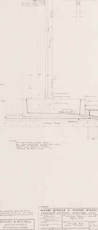
This image depicts a detailed architectural drawing that is part of a construction plan. It includes several views and sections of a specific architectural element, which appears to be a wall or a fence with vertical slats or boards. Here’s a closer look at each component: 1. Top Left Section: - A frontal elevation view showing vertical slats or boards. The slats are uniformly spaced and aligned, held together by two horizontal beams placed across the slats. This view is labeled with dimensions and notes. 2. Bottom Left Section: - A plan view (top-down view) showing the layout of the vertical slats and the horizontal beams. It includes annotations for the specific parts and dimensions to provide clear measurements. 3. Center Right Section: - A vertical section showing the side view of the slats, supporting beams, and foundation details. This section highlights how the elements are anchored and connected to the ground or foundation. 4. Additional small elements: - Smaller detailed sketches illustrate specific construction aspects such as joints, fixtures, and connections between different components. They provide further clarity on how to assemble the structure. 5. Title Block (Bottom Right): - The title block contains information about the architects and the project. It mentions that the drawing is part of the design for the "Frieda Fisher House" by architects Walter Gropius & Marcel Breuer. The architecture firm is Ritchey & Mitchell from Pittsburgh, Pennsylvania. It also includes the drawing number (475/275) and revision notes. The overall drawing is meticulously annotated with measurements and construction notes, providing essential instructions for building the architectural element.
Anthropic Claude
Created by claude-3-haiku-20240307 on 2024-12-30
This image appears to be a detailed engineering diagram or technical drawing. It contains various schematic representations, measurements, and annotations related to some type of mechanical or structural design. The drawing seems to be for a product or device called "Ritchey & Mitchell" based on the label at the bottom. The overall layout and style suggest this is an architectural, engineering, or technical blueprint or plan, though I cannot determine the specific purpose or application from the information provided in the image alone.
Created by claude-3-opus-20240229 on 2024-12-30
The image shows architectural drawings or blueprints for what appears to be a water trough and material basket, based on the title in the lower right corner. The drawings include front, side and top views with dimensions and construction details. The plans are hand-drawn with thin lines on graph paper or a similarly gridded background. Some handwritten notes and calculations are included alongside the precisely drafted schematics and diagrams.
Created by claude-3-5-sonnet-20241022 on 2024-12-30
This appears to be an architectural or engineering drawing showing detailed plans for what looks like a fence or gate construction. The drawing includes multiple views - elevation, plan, and detail views - with specific measurements and construction notes. The sketch is rendered in pencil or light ink on what appears to be drafting paper. The drawing shows: 1. A front elevation view of a fence section with vertical slats 2. A side/profile view showing the foundation and mounting details 3. A top-down plan view showing the layout 4. Various construction details and measurements The drawing has a professional title block in the bottom right corner indicating it was created by Ritchey & Mitchell from Pittsburgh, Pennsylvania. It appears to be a professional architectural or engineering document, likely used for construction purposes. The drawing style and format suggests this is likely a mid-20th century document, given its hand-drawn nature and traditional drafting techniques used.
Meta Llama
Created by us.meta.llama3-2-11b-instruct-v1:0 on 2025-03-13
The image depicts a technical drawing of a building's floor plan and elevation, showcasing the architectural design of the structure. The drawing is presented in a light gray color scheme on a white background, with various sections and details labeled and annotated. **Key Features:** * **Floor Plan:** The floor plan is divided into different rooms and spaces, including a living room, kitchen, dining room, bedrooms, and bathrooms. Each room is labeled and has its own unique characteristics, such as doorways, windows, and furniture placement. * **Elevation:** The elevation drawing shows the exterior of the building, including the walls, windows, doors, and roof. The drawing also includes details about the materials used, such as the type of brick or stone used for the walls. * **Labels and Annotations:** Throughout the drawing, there are various labels and annotations that provide additional information about the design. These include notes about the materials used, the dimensions of the rooms, and the location of specific features such as plumbing and electrical outlets. * **Scale:** The drawing includes a scale at the bottom, which allows the viewer to measure the size of the rooms and spaces in relation to each other. * **Authorship:** The drawing is attributed to Walter Gropius and Marcel Breuer, two renowned architects who were known for their modernist designs. **Overall:** The technical drawing provides a detailed and accurate representation of the building's design, allowing architects, engineers, and contractors to visualize and understand the layout and features of the structure. The drawing is a valuable tool for construction and renovation projects, as it helps to ensure that the final product meets the intended design specifications.
Created by us.meta.llama3-2-90b-instruct-v1:0 on 2025-03-13
The image presents a technical drawing of a structure, likely an architectural plan or blueprint. The drawing is rendered in black ink on a white background and features various lines, symbols, and notations that provide detailed information about the design. **Key Features:** * **Grid System:** A grid system is visible throughout the drawing, comprising horizontal and vertical lines that intersect to form squares. This grid likely serves as a reference point for measuring distances and angles within the design. * **Structural Elements:** Several structural elements are depicted in the drawing, including beams, columns, and walls. These elements are represented by solid lines, while dashed lines indicate hidden or obscured features. * **Dimensions and Notations:** Various dimensions and notations are scattered throughout the drawing, providing specific measurements and details about the design. These notations include numbers, letters, and symbols that correspond to different aspects of the structure. * **Scale and Orientation:** A scale is provided in the bottom-right corner of the drawing, indicating the ratio of the drawing to the actual size of the structure. The orientation of the drawing is also specified, with arrows pointing towards the top and bottom of the page. * **Title Block:** A title block is located in the bottom-left corner of the drawing, containing information about the project, including the name of the architect, the date, and the location. **Overall Impression:** The image appears to be a detailed technical drawing of a structure, likely created by an architect or engineer. The use of a grid system, structural elements, dimensions, and notations suggests a high level of precision and attention to detail. The inclusion of a scale and orientation further emphasizes the importance of accuracy in the design process. Overall, the image provides a comprehensive view of the structure's design and layout.
Amazon Nova
Created by amazon.nova-lite-v1:0 on 2025-01-13
The image appears to be an architectural drawing or blueprint for a house or building. The drawing contains various lines, shapes, and annotations that provide details about the structure's design and construction. Here is a detailed description of the image: 1. The drawing is divided into several sections, each representing a different part of the building. The top section shows a series of vertical lines, possibly indicating the layout of a wall or partition. 2. Below the top section, there is a rectangular shape with a cross-section view, likely representing a window or door opening. The dimensions and details of the opening are provided in the drawing. 3. The middle section of the drawing contains a floor plan or layout of the building. It shows various rooms and their relative positions, as well as the dimensions of each room. 4. The bottom section of the drawing includes details about the foundation, walls, and roof of the building. It shows the materials and construction techniques to be used for each part of the structure. 5. The drawing also includes annotations and notes in the margins, providing additional information about the design and construction process. These notes may include specifications for materials, dimensions, and other technical details. 6. The drawing is labeled with the names of the architects, "Ritchey & Mitchell," and the location, "Pittsburgh, Pennsylvania." This suggests that the drawing was created by these architects for a project in Pittsburgh. 7. The drawing appears to be a revision or update to an earlier version, as indicated by the notation "Revisions: 2/3/60" in the bottom right corner. This suggests that the architects made changes or updates to the original design. Overall, the image is a technical drawing that provides detailed information about the design and construction of a building or house. It includes various sections and annotations that help architects, engineers, and construction workers understand the structure's layout, dimensions, and materials.
Created by amazon.nova-pro-v1:0 on 2025-01-13
The image appears to be a technical drawing or blueprint of a construction project. It shows various architectural and structural details, including walls, beams, and support structures. The drawing is divided into different sections, each depicting a specific aspect of the project. The overall layout and design suggest a complex and intricate construction plan, likely for a large-scale building or infrastructure project.
Text analysis
Amazon