Machine Generated Data
Tags
Color Analysis
Categories
Imagga
| text visuals | 100% | |
Captions
Microsoft
created on 2018-03-22
| a close up of text on a white background | 79.1% | |
| a close up of text on a black background | 73.2% | |
| a close up of text on a white surface | 73.1% | |
OpenAI GPT
Created by gpt-4 on 2025-03-08
The image shows a technical architectural drawing or blueprint. This is a hand-drawn sketch with annotations and various views of details regarding some construction elements. The drawing includes several sectional views, which means the drawing represents slices through the construction to show how it is built. There are detailed notes and dimensions specifying materials and construction techniques, and these notes appear to be written in pencil. We can see terms like "sheathing," "plywood," "framing," and "insulation," which indicates the drawing may be focused on detailing the building's envelope or wall assembly. The layout is organized, with different sections labeled and with clear lines defining the boundaries of each detail. Some sections provide a more zoomed-in view to give specific sizes and instructions for construction. The drawing reflects a stage in the design process where the architect was working through the details of how parts of the building would be assembled, which is critical for guiding the construction process. On the top right corner, there is some text that appears to be the drawing's title block, which traditionally contains information about the project, the architect(s), the scale of the drawing, and the date. This part of the image is not clear enough to read the exact details, but it typically includes the name and address of the architectural firm, the project name, and may include details such as the drawing number and revision history.
Created by gpt-4o-2024-05-13 on 2025-03-08
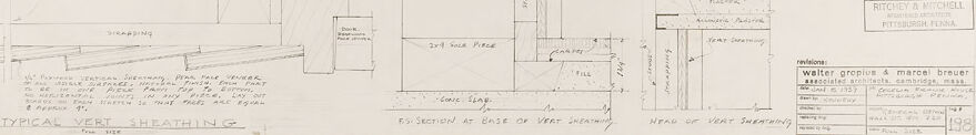
This image is an architectural drawing of the "Typical Vert Sheathing" provided by the architectural firm of Ritchey & Mitchell, in collaboration with the renowned architects Walter Gropius and Marcel Breuer. The drawing is technical and detailed, indicating various structural and construction elements pertaining to the vertical sheathing of a building. The top left of the drawing shows a large curved section, which likely represents a part of the sheathing assembly. Annotations and measurements indicate the precise placement and dimensions of various components. Several detailed cross-sectional views are presented, showing the layers and connections of materials within the sheathing. Each section is carefully labeled with dimensions and notations, indicating materials like sheathing, framing, plaster, and pavers. Specific details such as joints, base of vert sheathing, and head of vert sheathing are also elaborated upon to provide clarity on assembly requirements. On the bottom right corner, the title block confirms the firms involved and provides project details, including the sheet number (Sheet No. 39). Additionally, the title block includes signatures, project dates, and approval stamps, further authenticating the drawing as an official construction document. Overall, this detailed technical drawing is essential for guiding the construction or installation of the vertical sheathing in a building project, ensuring precision and adherence to design specifications.
Anthropic Claude
Created by claude-3-haiku-20240307 on 2024-12-30
This image appears to be an architectural or engineering drawing or diagram. It contains various technical sketches, measurements, and annotations that seem to be part of a larger schematic or design plan. The drawing includes different views, sections, and details of what looks like some kind of structure or object. There are no human figures or faces visible in this image.
Created by claude-3-opus-20240229 on 2024-12-30
The image shows a technical drawing or blueprint of what appears to be a water groove and meter detail, based on the title at the bottom right. The drawing includes various measurements, annotations, and cross-sectional views to provide specifications for constructing or installing this water-related component. The schematic style with precise dimensioning and labeling is typical of engineering drawings used to communicate designs for fabrication and assembly.
Created by claude-3-5-sonnet-20241022 on 2024-12-30
This image appears to be an architectural drawing or technical blueprint showing various cross-sectional views and details. It includes several elevation drawings and sections that appear to be focusing on wall construction or structural details. The drawing is done in pencil on what looks like drafting paper, with multiple views showing different aspects of the construction. There are dimension lines and notes scattered throughout the drawing, though they're not clearly legible in this reproduction. The drawing has a title block in the bottom right corner, which is typical of architectural drawings, and includes what appears to be "TYPICAL VERTICAL SECTION" notation at the bottom of one of the views. The overall style suggests this is a professional architectural or engineering document used for construction or documentation purposes.
Meta Llama
Created by us.meta.llama3-2-11b-instruct-v1:0 on 2025-03-15
The image depicts a technical drawing of a boat's hull, showcasing various views and measurements. The drawing is rendered in pencil on white paper and includes handwritten notes and labels. **Key Features:** * **Hull Shape:** The hull is depicted in multiple views, including side, top, and front perspectives. * **Measurements:** Various measurements are provided, including the length, width, and depth of the hull. * **Labeling:** Handwritten labels and notes are scattered throughout the drawing, likely indicating specific features or components of the boat. * **Technical Details:** The drawing includes technical details such as the shape of the keel, the location of the rudder, and the size of the portholes. * **Scale:** A scale is included in the bottom-right corner of the drawing, allowing for accurate measurements and scaling. **Overall Impression:** The drawing appears to be a detailed and accurate representation of a boat's hull, likely created for construction or design purposes. The level of detail and precision suggests that it was created by a skilled draftsman or engineer.
Created by us.meta.llama3-2-90b-instruct-v1:0 on 2025-03-15
The image presents a technical drawing of a structure, likely an architectural or engineering design. The drawing is rendered in pencil on a white background and features various lines, shapes, and annotations that provide detailed information about the structure's dimensions, materials, and construction methods. **Key Features:** * **Title:** "Typical Vent Sheathing" is written in the bottom-left corner, indicating that this drawing represents a standard design for vent sheathing. * **Dimensions:** The drawing includes measurements and dimensions, such as "2x4 STK" and "3x4 SULK PLATE," which suggest that the structure is composed of wooden framing members. * **Annotations:** Handwritten notes and annotations are scattered throughout the drawing, providing additional information about the structure's design and construction. These notes include references to specific materials, such as "Plywood" and "Fiberboard," and instructions for assembly and installation. * **Sectional Views:** The drawing includes sectional views of the structure, which show the relationships between different components and provide a clearer understanding of the overall design. * **Scale:** A scale bar is located in the bottom-right corner, allowing viewers to accurately measure the dimensions of the structure. **Overall Impression:** The technical drawing appears to be a detailed and precise representation of a vent sheathing design. The use of pencil and handwritten annotations suggests that this is a working drawing, possibly created during the design or construction phase of a project. The inclusion of sectional views and a scale bar indicates that the drawing is intended to be a comprehensive and accurate representation of the structure.
Amazon Nova
Created by amazon.nova-pro-v1:0 on 2025-02-27
The image is a technical drawing, likely an architectural or engineering blueprint, titled "Typical Vert Sheathing." The drawing is divided into several sections, each illustrating different components or perspectives of a structure. The top section shows a side view of a structure with measurements and labels indicating dimensions and features such as "Line of Iron at Back," "Line of Iron at Front," and "Line of Iron at Side." The middle section includes a detailed plan view with further annotations and measurements. The bottom section features a perspective view, possibly showing the assembly or construction details of the structure. The drawing is annotated with various notes and measurements, indicating precise specifications for construction or assembly. The title "Typical Vert Sheathing" suggests that this blueprint is a standard design for vertical sheathing, a common element in construction.
Created by amazon.nova-lite-v1:0 on 2025-02-27
The image appears to be an architectural drawing or blueprint of a structure. The drawing depicts various sections and details of the structure, including: - Vertical sheathing: The drawing shows vertical sheathing with measurements and specifications. It includes details such as the type of sheathing, dimensions, and placement. - Typical vertical sheathing: There is a section labeled "Typical Vertical Sheathing" that provides additional details about the sheathing material and its application. - Section at base of vertical sheathing: The drawing includes a section view at the base of the vertical sheathing, showing the connection and support details. - Head of shear supporting: There is a section labeled "Head of Shear Supporting," which likely refers to the support structure for shear forces in the building. - Revisions: The drawing includes a revision section with notes and changes made to the original design. - Signatures and stamps: The drawing has signatures and stamps from various individuals and organizations, indicating approval and verification of the design. Overall, the image appears to be a detailed architectural drawing or blueprint for a structure, providing information about the materials, dimensions, and construction details.
Text analysis
Amazon