Machine Generated Data
Tags
Color Analysis
Feature analysis
Amazon
Clarifai

AWS Rekognition
| Boat | 86.9% | |

Categories
Imagga
created on 2018-03-22
| text visuals | 99.9% | |
| paintings art | 0.1% | |
Captions
Microsoft
created by unknown on 2018-03-22
| a close up of a map | 81.1% | |
| close up of a map | 78% | |
| a map with text | 71.1% | |
Clarifai
No captions written
Salesforce
Created by general-english-image-caption-blip on 2025-05-11
a photograph of a drawing of a boat on a white background
Created by general-english-image-caption-blip-2 on 2025-06-29
a drawing of a space shuttle with a plan
OpenAI GPT
Created by gpt-4 on 2025-03-06
The image appears to be an architectural drawing or blueprint of a building plan. This technical drawing includes a layout with annotations, measurements, and specifications. The structure seems to have a somewhat triangular or trapezoidal shape with clearly defined rooms and spaces within.
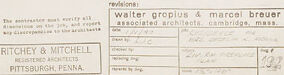
To the lower right corner, there are names that could potentially be of the architects or firms involved in the design, but I won't specify them to comply with the guidelines. There are also some boxes that likely contain project details such as revision information, drawing number, and possibly the title of the project.
Different sections of the plan are labeled, typically indicating the purpose or the name of the space, and there may be indications of material specifications or construction notes dispersed throughout the drawing. The lines are neatly drawn, suggesting a professional and precise approach to the design process.
Created by gpt-4o-2024-05-13 on 2025-03-06
The image displays an architectural blueprint, which is a detailed technical drawing of a building's design. The blueprint seems to depict the layout of a structure that has a unique, curved shape. Specific sections within the layout are labeled with dimensions and notes, potentially indicating different rooms or areas of the building.
Labeling at the bottom right corner identifies the architectural firms involved in the design as "Ritchey & Mitchell" and "Walter Gropius & Marcel Breuer" from Cambridge, Massachusetts. Additionally, it notes that the blueprint was created in Pittsburgh, Pennsylvania. The document is a product of a detailed and precise planning process typical in architecture, aimed at translating an architectural concept into a buildable project.
Anthropic Claude
Created by claude-3-haiku-20240307 on 2024-12-30
The image appears to be a technical drawing or blueprint of some kind of mechanical or engineering design. It shows detailed schematics and measurements for a structure or object, likely an aircraft or spacecraft component. The drawing includes labels, dimensions, and other technical specifications, indicating it is a detailed engineering diagram rather than a visual representation. There are no human faces or identifiable individuals shown in this image.
Created by claude-3-opus-20240229 on 2024-12-30
The image shows a technical drawing or blueprint of what appears to be a cross-section view of an aircraft or spacecraft. The drawing includes various measurements, annotations, and structural details. The shape resembles a flying wing or blended wing body design. In the lower right corner, there is a title block with text that says "Ritchey & Mitchell Pittsburgh, Penna." along with some additional details that are a bit hard to make out given the image resolution. Overall, it looks like an engineering schematic depicting the internal structure and dimensions of an advanced aeronautical or aerospace vehicle design.
Created by claude-3-5-sonnet-20241022 on 2024-12-30
This image appears to be an architectural or technical drawing, specifically showing what looks like the half-plan view of a boat or vessel design. The drawing is done in a professional drafting style with clean lines and measurements. The plan shows both the upper and lower parts of the vessel's cross-section, with various compartments and spaces clearly marked out. The design has a distinctive curved hull shape that comes to points at both ends, and there appears to be a raised central section. The drawing includes detailed measurements and notations throughout, and has a title block in the bottom right corner that appears to be from an architectural or design firm. The overall style suggests this is a professional blueprint or technical specification drawing, likely used in the construction or documentation of the vessel.
Created by us.anthropic.claude-3-5-sonnet-20241022-v2:0 on 2025-06-26
This image appears to be an architectural or technical drawing, specifically a floor plan or layout diagram. It shows what appears to be a symmetrical design with a triangular or pointed shape at the top and wing-like extensions on either side. The drawing includes various rectangular sections and compartments with measurements and annotations. The style is typical of professional architectural blueprints, drawn in fine lines on a light background. At the bottom of the drawing, there appears to be a title block or information panel with what looks like project details or specifications. The drawing has a professional, technical quality and appears to be part of a larger set of architectural plans.
Meta Llama
Created by us.meta.llama3-2-11b-instruct-v1:0 on 2025-03-13
The image presents a technical drawing of a building, likely a house or a small structure, with a detailed floor plan and various annotations. The drawing is rendered in pencil on white paper, featuring a central axis that divides the structure into two halves.
- Central Axis
- The central axis is labeled as the "HALF-PLAN (LOWER PART)" and "HALF-PLAN (UPPER PART)".
- It appears to be a vertical line that runs through the center of the building, dividing it into two symmetrical halves.
- Floor Plan
- The floor plan shows the layout of the building's interior, including rooms, corridors, and other features.
- The plan is drawn to scale, with measurements and dimensions included for each room and feature.
- Annotations
- The drawing includes various annotations and notes, such as labels, arrows, and symbols.
- These annotations likely provide additional information about the building's design, construction, and functionality.
- Scale
- The scale of the drawing is not explicitly stated, but it appears to be a 1:100 or 1:50 scale.
- This means that each unit of measurement on the drawing represents a real-world measurement of 100 or 50 units, respectively.
- Authorship
- The drawing is attributed to Walter Gropius and Marcel Breuer, two renowned architects.
- The drawing is likely a part of their portfolio or a design project that they worked on together.
- Location
- The drawing is dated 1925 and is located in Pittsburgh, Pennsylvania.
- This suggests that the building was designed and constructed in the mid-20th century, during a time of significant architectural innovation and experimentation.
In summary, the image presents a technical drawing of a building, likely a house or a small structure, with a detailed floor plan and various annotations. The drawing is attributed to Walter Gropius and Marcel Breuer, two renowned architects, and is dated 1925. The drawing provides valuable insights into the design and construction of the building, as well as the architectural style and trends of the time.
Created by us.meta.llama3-2-90b-instruct-v1:0 on 2025-03-13
The image presents a technical drawing of a building's floor plan, showcasing the architectural design and layout. The drawing is rendered in black ink on a white background, with various lines, symbols, and annotations that provide detailed information about the building's structure and features.
Key Features:
- Floor Plan: The central focus of the image is the floor plan, which depicts the building's layout, including rooms, corridors, and other spaces.
- Annotations: Throughout the drawing, there are numerous annotations that provide additional information about the building's design, such as room labels, door and window locations, and measurements.
- Symbols: Various symbols are used throughout the drawing to represent different elements, such as electrical outlets, plumbing fixtures, and HVAC systems.
- Scale: The drawing includes a scale indicator, which allows viewers to understand the relative sizes of the different components.
- Title Block: In the bottom-right corner, a title block provides information about the project, including the name of the architect, the location, and the date.
Overall Impression:
The image provides a detailed and informative representation of the building's design, showcasing the architect's attention to detail and commitment to creating a functional and aesthetically pleasing space. The use of clear and concise annotations, symbols, and scales makes it easy for viewers to understand the building's layout and features.
Amazon Nova
Created by amazon.nova-lite-v1:0 on 2025-01-12
The image appears to be a technical drawing or blueprint of a building or structure. The drawing is divided into two sections, labeled "Half-Plan (Upper Part)" and "Half-Plan (Lower Part)." The drawing shows various lines, dimensions, and labels indicating the layout and measurements of the structure.
The upper half of the drawing depicts the upper part of the structure, while the lower half shows the lower part. The drawing includes details such as the floor plan, wall thickness, and other structural elements. The drawing is labeled with the name of the architects, Walter Gropius and Marcel Breuer, and their location, Cambridge, Massachusetts.
The drawing also includes a revision section, indicating that the design has undergone changes or updates. The revision section includes details such as the date of the revision, the name of the person responsible for the revision, and the reason for the revision.
Overall, the image appears to be a technical drawing or blueprint of a building or structure designed by Walter Gropius and Marcel Breuer, with revisions made to the original design.
Created by amazon.nova-pro-v1:0 on 2025-01-12
The image shows a large architectural blueprint drawing of a building. The drawing is done in black ink on white paper. The building has a unique design, with a central rectangular shape and two wings extending outwards. The wings have a curved shape, with the upper part of the wings being wider than the lower part. The building appears to be a commercial or industrial structure, possibly a factory or warehouse.
Google Gemini
Created by gemini-2.0-flash on 2025-05-12
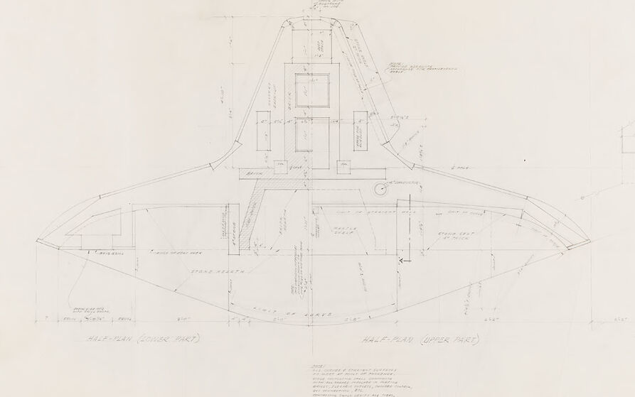
The image is an architectural drawing, specifically a half-plan of a building's lower and upper parts. The drawing is labeled "HALF-PLAN (LOWER PART)" and "HALF-PLAN (UPPER PART)." The drawing contains various dimensions and notes related to the building's design, materials, and construction. The architectural firm responsible for the design is listed as "RITCHEY & MITCHELL REGISTERED ARCHITECTS PITTSBURGH, PENNA." There is also a section for revisions, which indicates that Walter Gropius and Marcel Breuer, associated architects from Cambridge, Massachusetts, were involved in the project.
Created by gemini-2.0-flash-lite on 2025-05-12
Here's a description of the image:
Overall:
The image is an architectural drawing or plan, likely a blueprint, with intricate details drawn in fine lines. It appears to be a plan view, showing the layout of a structure from above. The drawing is labeled with various annotations, dimensions, and notes.
Key Elements:
- Shape: The central focus is a somewhat asymmetrical, curving shape with a prominent "V" or triangular section at the top. It could represent the floor plan of a building or a specific architectural element.
- Details: The drawing incorporates details such as walls, openings, possible furniture or built-in elements (like a fireplace), and dimensions (with numbers and units). Brickwork is indicated, and areas labeled as "stone hearth".
- Annotations: Numerous handwritten notes and labels clarify details, likely indicating materials, structural elements, and other specifications.
- Halves: The drawing is divided into "Half-Plan (Lower Part)" and "Half-Plan (Upper Part)".
Additional Notes:
- The bottom right corner has information related to the architects: "Walter Gropius & Marcel Breuer, Associated Architects, Cambridge, Mass."
- The firm "Ritchey & Mitchell, Registered Architects, Pittsburgh, Penna" is also mentioned.
- The drawing appears to be made on tracing paper.
In summary, this is a detailed architectural plan, most likely for a unique structure or element, that provides extensive information about its design and construction.
Mistral Pixtral
Created by us.mistral.pixtral-large-2502-v1:0 on 2025-05-30
The image is a detailed architectural blueprint of a building, specifically a sectional view. The drawing is labeled with various dimensions, annotations, and structural details. Here are some key observations:
Building Shape and Structure:
- The building has a distinctive shape, with a central vertical section and two large, sloping sides that extend outward.
- The central part of the structure appears to be multi-storied, with several floors indicated by horizontal lines.
Sections and Labels:
- The blueprint is divided into two main sections: the "Section (Lower Part)" on the left and the "Half-Section (Upper Part)" on the right.
- Various parts of the building are labeled, such as "Stone Seating," "Stone Steps," "Stone Wall," and "Steel Columns."
Materials and Construction Details:
- The blueprint specifies the use of different materials like stone and steel for various parts of the structure.
- There are detailed measurements and annotations indicating the dimensions and placement of structural elements.
Architectural Firm:
- The blueprint is credited to the architectural firm "Rutchey & Mitchell" from Pittsburgh, Pennsylvania.
- The names "Walter Gropius & Marcel Breuer" are mentioned as associated architects, indicating their involvement in the design.
Date and Drawing Number:
- The drawing is dated October 1940.
- It is labeled with the drawing number "22" and a sheet number "2 of 3."
This blueprint provides a comprehensive view of the building's internal structure and design, highlighting the architectural and engineering details necessary for construction.
Qwen
No captions written
Text analysis
Amazon