Machine Generated Data
Tags
Color Analysis
Feature analysis
Amazon
Clarifai
AWS Rekognition
| Document | 81.2% | |

Categories
Imagga
created on 2018-03-22
| text visuals | 98.2% | |
| paintings art | 1.7% | |
| food drinks | 0.1% | |
Captions
Microsoft
created by unknown on 2018-03-22
| a close up of text on a whiteboard | 72.6% | |
| a close up of a whiteboard | 70.9% | |
| close up of text on a whiteboard | 69.1% | |
Clarifai
No captions written
Salesforce
Created by general-english-image-caption-blip on 2025-05-11
a photograph of a drawing of a plan for a house
Created by general-english-image-caption-blip-2 on 2025-06-29
a drawing of a building with plans and drawings
OpenAI GPT
Created by gpt-4 on 2025-03-08
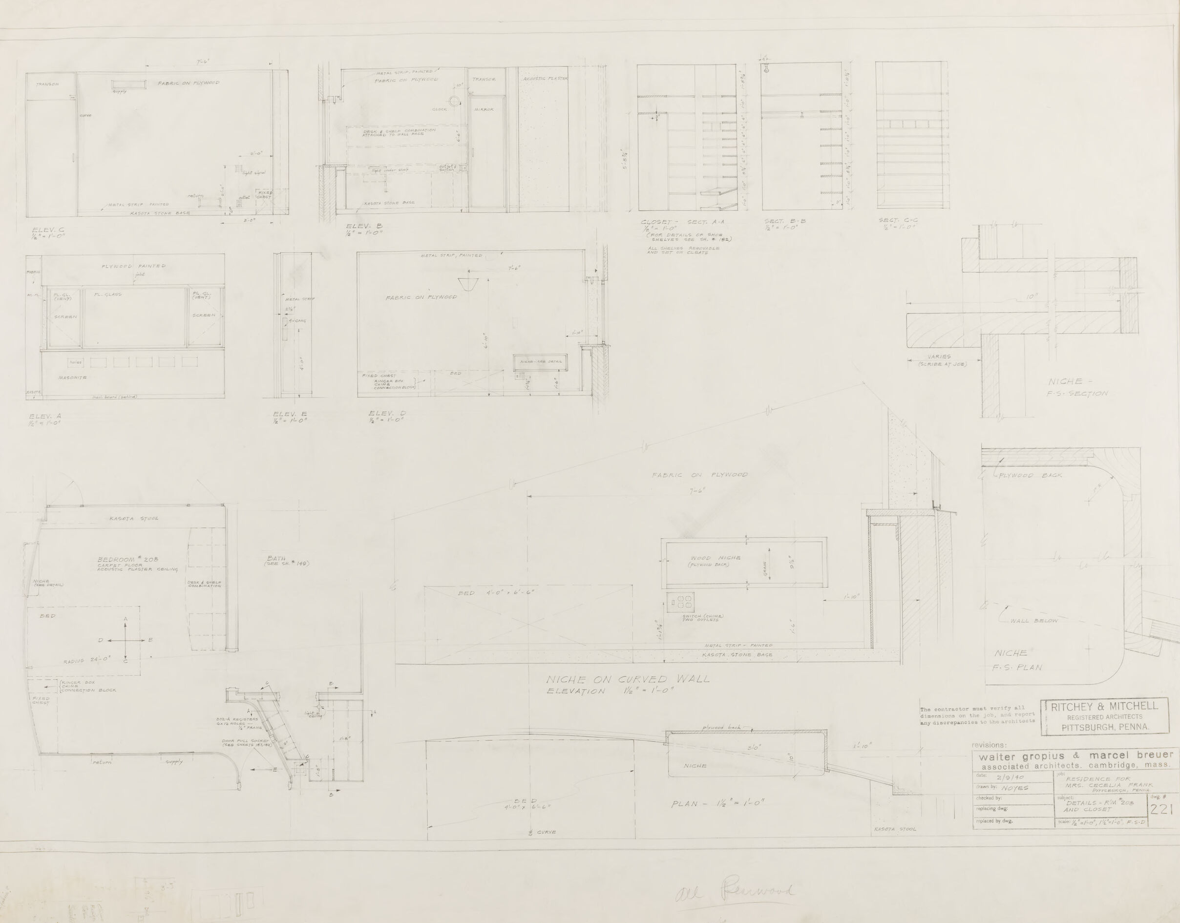
The image displays an architectural drawing that includes several detailed plans and elevations of various elements of a building or structure. There are dimensions and notes provided, which are typical in architectural blueprints to guide the construction or manufacturing process. This drawing likely serves as a technical communication between the architects, engineers, and builders. It contains numerous technical annotations, measurements, and cross-sections. At the bottom right corner, there's a title block that includes the names of individuals and an organization, possibly the architects or firm responsible for the design, the project title, and location details. The drawing is quite detailed, and the style indicates it may be from a time when such plans were drafted by hand rather than with computer-aided design (CAD) software.
Created by gpt-4o-2024-05-13 on 2025-03-08
This image shows a technical architectural drawing by Ritchey & Mitchell, edited by the design team of Walter Gropius and Marcel Breuer, two prominent architects and designers associated with modernist architecture. The drawing contains detailed elevations, sections, plans, and construction details for various architectural elements.
- Elevations – Side or front views of walls and structures are depicted to show height and design features.
- Sections – Cross-sectional views detail the internal composition, materials, and structural components.
- Plans – Overhead views map the layout of various spaces, such as rooms and niches.
- Construction Details – Specifics about joinery, materials, and dimensions are provided for precise construction.
The technical drawing is clearly labeled and includes handwritten notes, dimensions, and annotations for clarity. Box titles such as "NICHE ON CURVED WALL" indicate the focal elements of the design. Details are rendered in pencil, providing a clear and meticulous representation consistent with architectural drafting standards. The title block includes comprehensive information about the drawing, including the project number, drawing number, and a brief project description, lending it a formal and professional appearance.
The drawing conveys a sophisticated understanding of modernist design principles and functionality, essential for accurately executing the architectural vision on-site.
Anthropic Claude
Created by us.anthropic.claude-3-5-sonnet-20241022-v2:0 on 2025-06-24
This image appears to be an architectural drawing or blueprint showing various floor plans and elevations. The drawing includes multiple detailed sketches of what seems to be interior layouts and wall sections. At the bottom of the drawing, there are title blocks indicating this is from architectural firms "Ritchey & Mitchell" and "Walter Gropius & Marcel Breuer" from Cambridge, Mass. The drawings show various scales and measurements, with detailed annotations and dimensions. The plans appear to be technical in nature, showing room layouts, wall sections, and other architectural details. The document appears to be vintage or historical, given its hand-drawn nature and aged appearance of the paper.
Created by claude-3-haiku-20240307 on 2024-12-31
This image appears to be an architectural blueprint or technical drawing. It contains various detailed plans, elevations, and sections of what seems to be a building or structure. The drawing includes measurements, annotations, and technical details, suggesting it is a design or construction document. The overall layout and style of the drawing indicate it is likely a professional architectural or engineering plan.
Created by claude-3-opus-20240229 on 2024-12-31
The image shows architectural drawings and floor plans for what appears to be a building called "Walter Gropius & Marcel Breuer Associated Architects, Little Carnegie Hotel". The plans depict various floor layouts and elevations with dimensions and annotations. The drawings are rendered in graphite or pencil on off-white paper. The architectural firm "Richey & Mitchell" is credited at the bottom right of the plans.
Created by claude-3-5-sonnet-20241022 on 2024-12-31
This image appears to be an architectural drawing or blueprint showing various detailed plans and elevations for what seems to be interior design elements, particularly focused on a niche or built-in wall feature. The drawing includes multiple views and cross-sections from different angles, with precise measurements and dimensions noted throughout. The drawing is signed by the architectural firm Ritchey & Mitchell from Pittsburgh, and also references Walter Gropius and Marcel Breuer as associated architects from Cambridge, Mass. The drawing consists of several smaller sketches arranged on a single sheet, showing different aspects and details of the design, including plan views, elevations, and detail drawings. The sketches are done in a technical drafting style typical of architectural drawings, with clean lines and precise measurements.
Meta Llama
Created by us.meta.llama3-2-11b-instruct-v1:0 on 2025-03-15
The image presents a detailed floor plan for a residence, showcasing the layout and design of the interior spaces. The plan is drawn on a large sheet of paper, with various rooms and areas labeled and dimensioned.
- Overall Layout:
- The floor plan is divided into several sections, each representing a different level or area of the residence.
- The plan includes multiple rooms, corridors, and staircases, providing a comprehensive view of the home's layout.
- Room Dimensions:
- Each room is labeled with its dimensions, including length, width, and height.
- The dimensions are provided in feet and inches, allowing for precise measurement and planning.
- Doors and Windows:
- The plan includes detailed drawings of doors and windows, including their size, shape, and location.
- The doors and windows are labeled with their corresponding room numbers, making it easy to identify their location within the floor plan.
- Staircases:
- The plan features multiple staircases, each with its own unique design and layout.
- The staircases are labeled with their corresponding room numbers, ensuring that they connect to the correct areas of the residence.
- Corridors:
- The plan includes several corridors, which connect different rooms and areas of the residence.
- The corridors are labeled with their corresponding room numbers, making it easy to navigate the floor plan.
- Special Features:
- The plan includes several special features, such as a fireplace, a wet bar, and a built-in bookshelf.
- These features are labeled and dimensioned, providing a detailed understanding of their design and placement within the floor plan.
In summary, the image presents a comprehensive floor plan for a residence, showcasing its layout, design, and various features. The plan is detailed and precise, providing a clear understanding of the home's interior spaces and their relationships to one another.
Created by us.meta.llama3-2-90b-instruct-v1:0 on 2025-03-15
The image depicts a technical drawing of a building's floor plan, featuring various rooms and spaces. The drawing is rendered in pencil on a light-colored paper background, with the title "NICHE ON CURVED WALL" prominently displayed at the bottom center.
Key Features:
- Title: "NICHE ON CURVED WALL" (bottom center)
- Drawing Style: Pencil on light-colored paper
- Content: Floor plan of a building with multiple rooms and spaces
Additional Details:
- Scale: Not explicitly stated, but appears to be a detailed representation of the building's layout
- Annotations: Various notes and labels throughout the drawing, likely indicating specific features or dimensions
- Paper Condition: Appears to be aged or worn, with visible creases and tears along the edges
Overall, the image presents a detailed and technical representation of a building's floor plan, showcasing the architect's design intent and attention to detail.
Amazon Nova
Created by amazon.nova-pro-v1:0 on 2025-01-13
The image depicts a set of architectural blueprints or floor plans, likely for a residential or commercial building. The blueprints are arranged in a grid format, with each section representing a different part of the building. The blueprints are drawn in black ink on a white background. The blueprints show the layout of the rooms, including the size and shape of each room, as well as the location of doors, windows, and other features. The blueprints also include measurements and notes, indicating the scale and dimensions of the building. The blueprints are likely used by architects, engineers, or construction workers to plan and design the building.
Created by amazon.nova-lite-v1:0 on 2025-01-13
The image is of a page from a book or a document containing architectural drawings. The page has a title at the top that reads "Ritchey & Mitchell, Pittsburgh, Penna." and "Walter Gropius & Marcel Breuer, Associated Architects, Cambridge, Mass." The page contains several architectural drawings, including floor plans, elevations, and sections of a building. The drawings are labeled with dimensions, measurements, and notes, indicating that they are detailed and precise. The drawings show a modern building with clean lines and simple shapes, reflecting the Bauhaus style of architecture. The page also contains a table with measurements and notes, as well as a signature at the bottom.
Google Gemini
Created by gemini-2.0-flash on 2025-05-27
Here's a description of the image:
The image shows an architectural drawing, likely a blueprint, of a design. It's rendered in a light blue or gray color, giving it a vintage or technical feel. The drawing includes various elevations, sections, and plans, indicating different perspectives and details of the design.
Text within the drawing includes labels like "ELEV" (likely denoting elevation views) and dimensions in feet and inches, typical in architectural plans. The title "NICHE ON CURVED WALL ELEVATION" suggests a focus on a curved niche within a wall.
In the lower right corner, there's a title block with the name "RITCHEY & MITCHELL REGISTERED ARCHITECTS PITTSBURGH, PENNA," indicating the firm that created the drawing. It also mentions "walter gropius & marcel breuer associated architects cambridge, mass," suggesting a collaboration or association with these well-known architects. The drawing number "221" is also listed.
Overall, the image presents a detailed and technical architectural drawing, likely dating back to a period when hand-drafting was the norm.
Created by gemini-2.0-flash-lite on 2025-05-27
This is a technical drawing, likely an architectural plan or design. It's a detailed sketch with precise measurements and annotations. The drawing seems to focus on the interior design, particularly on specific elements like a "NICHE" on a curved wall. There are multiple elevations (views from different angles) showing details of the design. There are sections and plan views (top-down views). The title block provides context like the architects (Ritchey & Mitchell, Walter Gropius & Marcel Breuer) and potentially the project's name.
Mistral Pixtral
Created by us.mistral.pixtral-large-2502-v1:0 on 2025-05-31
The image is an architectural blueprint or technical drawing. It appears to be a detailed plan for a building or structure, likely a residential or commercial property. Here are some key observations:
Title and Information Block:
- The bottom right corner contains a title block with the name "RITCHEY & MITCHELL" and the location "PITTSBURGH, PENNA."
- The drawing is dated "6-17-07."
- There is a note indicating that the drawing is not to be reproduced without written permission.
- The drawing is identified as "Sheet 1 of 1."
- The scale of the drawing is noted as "1/4" = 1'-0".
- There is a signature and a stamp, indicating approval or authorship.
Drawing Details:
- The drawing includes various elevations and sections of the building.
- There are multiple views, including front, side, and rear elevations.
- Detailed measurements and dimensions are provided for different parts of the structure.
- The layout includes walls, windows, doors, and other architectural elements.
- There are annotations and labels indicating specific features and materials.
Sections and Elevations:
- The drawing includes different sections and elevations, such as the "Section on Center Wall" and "Elevation."
- These sections provide detailed views of the internal structure and layout.
- The plans show the arrangement of rooms, staircases, and other internal features.
Materials and Construction Notes:
- The drawing includes notes on materials and construction methods.
- There are references to specific materials like "brick" and "concrete."
- Construction details are provided for various elements, such as foundations, walls, and roof structures.
Additional Notes:
- There are handwritten annotations and corrections in some areas, indicating revisions or additional details.
- The drawing is detailed and precise, suggesting it is a professional architectural plan.
Overall, the image is a comprehensive architectural blueprint providing detailed information about the design and construction of a building.
Qwen
Created by Qwen/Qwen2.5-VL-7B-Instruct on 2025-07-20
This image is a detailed architectural drawing, likely a set of plans for a residential project. The document includes various elevations (views of the building from different angles), sections (views of the building cut in half to show cross-sections), and details of specific design elements. Here are some key observations:
Elevations (Elev. A, Elev. B, Elev. C, Elev. D, Elev. E): These drawings show the front, back, and side views of the building, detailing the materials and construction methods like fabric on plywood, metal strip painted, and masonry work.
Sections (Sect. A-A, Sect. B-B, Sect. C-C): These drawings provide a view of the building's interior structure, showing details of the walls, floors, and other structural elements. They include details such as the placement of shelves, doors, and niches.
Niche Details: Several drawings focus on the design and placement of niches, both on curved walls and in sections of the building, providing dimensions and construction details for these spaces.
Materials and Finishes: The use of materials such as plywood, fabric, metal strips, and stone bases is extensively detailed, indicating the designer's focus on texture and layering.
Architects and Title: The document is attributed to Ritchey & Mitchell, a firm of registered architects from Pittsburgh, Pennsylvania. The project is for a residence and is part of Walter Gropius & Marcel Breuer's associated architecture firm in Cambridge, Massachusetts.
Revisions and Notes: The bottom right corner contains information about revisions, the date, and the architects’ details, suggesting this is a working document used for construction.
This type of detailed planning is crucial for ensuring that the architectural design is accurately executed and that all necessary elements are considered for the construction of the building.
Created by Qwen/Qwen2.5-VL-72B-Instruct on 2025-07-20
This image is a detailed architectural drawing or blueprint, likely for a residential space, specifically detailing the design of a bedroom with a curved wall. The drawing includes multiple elevation views (Elev. A, Elev. B, Elev. C, Elev. D, Elev. E) and sections (Sect. A-A, Sect. B-B, Sect. C-C) of the room, as well as a plan view of the niche on the curved wall.
Key features and materials specified in the drawing include:
- Fabric on Plywood: Used for the walls and possibly the ceiling.
- Kasota Stone Base: Mentioned for the wall base.
- Metal Strip Painted: Likely used for trim or decorative elements.
- Plywood Painted: Used for certain sections of the wall.
- Wood Niche with Plywood Back: Detailed in the plan and elevation views.
- Bed: Dimensions are specified as 4'-0" x 6'-6".
- Bath: Referenced in Elev. E but not detailed in this drawing.
- Desk and Shelf Combination: Mentioned in the bedroom section.
- Acoustic Plaster Ceiling: Specified for the ceiling.
- Switch (China) and Two Outlets: Located near the bed.
- Kasota Stone Base: Used for the wall base.
- Plywood Back: Mentioned in the niche details.
The drawing includes various dimensions and notes, such as the radius of the curved wall (24'-0") and the scale of the elevations and sections (1/2" = 1'-0"). The drawing is signed by Walter Gropius & Marcel Breuer, with Ritchey & Mitchell listed as the registered architects from Pittsburgh, Pennsylvania. The date of the drawing is 2/9/40, and it is for the residence of Mrs. Cecelia Frank.
The overall layout and details suggest a modern and functional design, with careful attention to materials and dimensions.
Text analysis
Amazon